Differential pressure indicator and method of manufacture

Active Publication Date: 2007-12-18
BALDWIN FILTERS
View PDF13 Cites 12 Cited by
  • Summary
  • Abstract
  • Description
  • Claims
  • Application Information

AI Technical Summary

Benefits of technology

[0005]The invention provides an improved differential pressure indicator and method of manufacture, through the use of components that allow for a differential pressure indicator having either open or closed logic by using substantially similar components. It is an aspect of the

Problems solved by technology

Unfortunately, to manufacture either an indicator that opens a circuit or an indicator that closes a circuit requires significantly different components and / or design from the other.

Method used


Image

  • Differential pressure indicator and method of manufacture
  • Differential pressure indicator and method of manufacture
  • Differential pressure indicator and method of manufacture

Examples


Embodiment Construction

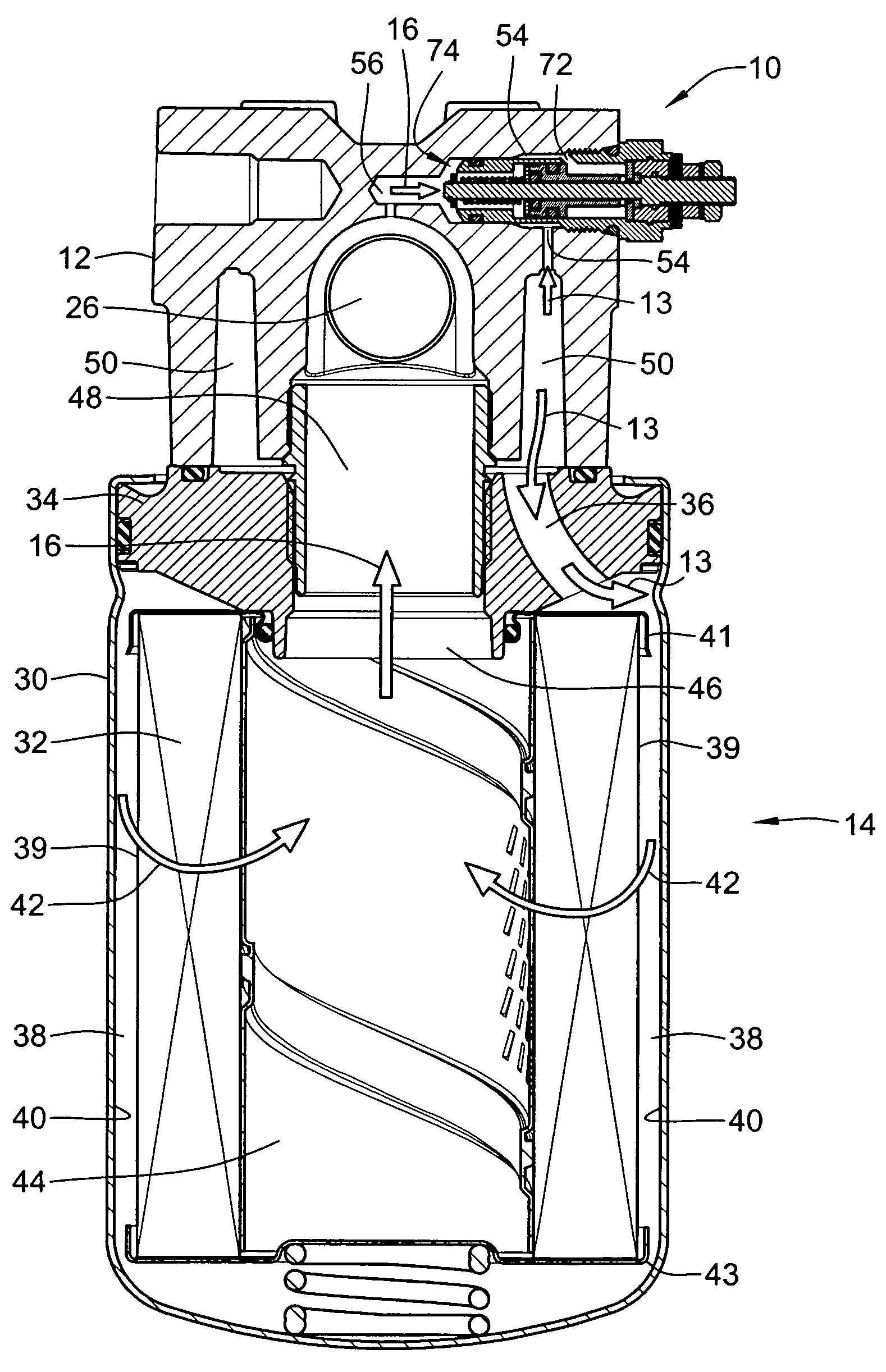
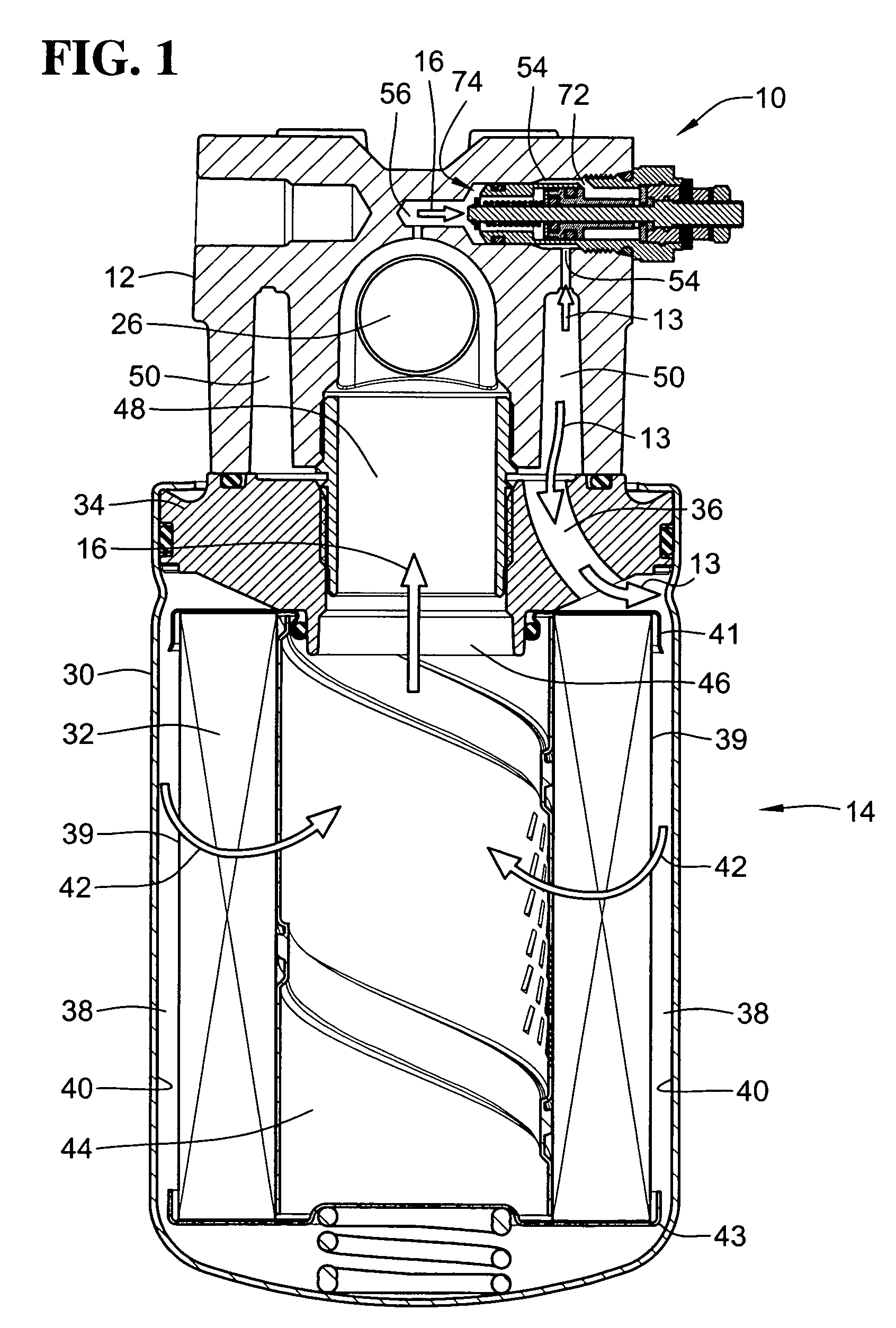
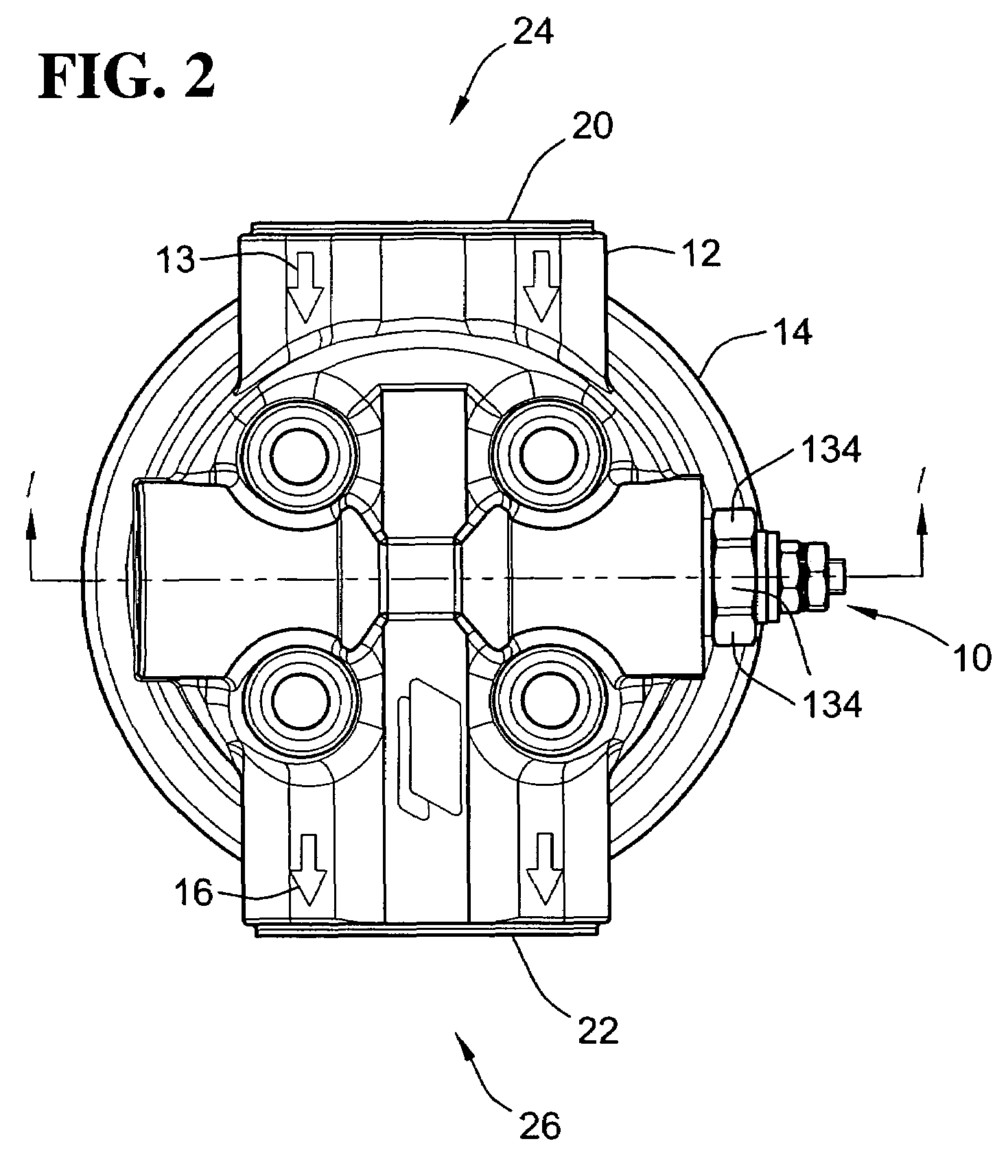
[0023]A differential pressure indicator 10 in accordance with the present invention is illustrated in FIG. 1. The differential pressure indicator 10 is threadedly secured to a filter head 12 to monitor or sense the pressure differential between a dirty fluid flow, indicated by arrows 13, upstream from a filter 14 and a clean fluid flow, indicated by arrows 16, downstream from the filter 14.

[0024]Illustrated in FIG. 2, the filter head 12 includes an inlet side 20 and an outlet side 22. The inlet side 20 includes an inlet port 24 that is connected to a dirty fluid supply (not shown), such as an engine, transmission and the like. The outlet side 22 includes an outlet port 26 that is connected to the dirty fluid supply to return the freshly filtered fluid back to the fluid supply.

[0025]The filter 14, as shown in FIG. 1, is a typical fluid filter and includes a housing in the form of a canister 30, made of metal or plastic, a cylindrical ring of filter media 32, and an end plate 34. Alth...


PUM

PropertyMeasurementUnit
Pressureaaaaaaaaaa
Responsivityaaaaaaaaaa

Abstract

A differential pressure indicator and method of configuring a differential pressure indicator is provided. The differential pressure indicator is configurable to provide open circuit or closed circuit logic and includes a housing, a pressure responsive element, a post, first, second and third electrical contacts and an electrical insulator from an insulative material. The electrical insulator separates the third electrical contact from either the first contact or the second contact to provide a desired type of logic. The differential pressure indicator may use substantially similar components to provide either open circuit or closed circuit logic or the components may be rearranged to provide either open circuit or closed circuit logic.

Description

FIELD OF THE INVENTION[0001]This invention generally relates to a differential pressure indicator. More particularly, the invention relates to a differential pressure indicator for a filtration system for indicating when to change or clean a fluid filter.BACKGROUND OF THE INVENTION[0002]In hydraulic circuits, differential pressure indicators are used to warn the operator that the filter is plugged and needs to be replaced or cleaned. These indicators sense the pressure differential between the fluid flow upstream from the filter and the fluid flow downstream from the filter. As the filter becomes increasingly plugged with contaminants filtered from the fluid, the restriction and the differential pressure between fluid upstream of the filter and fluid downstream of the filter increases.[0003]Typically, these indicators incorporate a spring loaded piston. One side of the piston is plumbed to the dirty fluid on the upstream side of the filter and the other side of the piston is plumbed...

Claims


Application Information

Patent Timeline
IPC IPC(8): G01L7/16
CPCB01D35/143H01H35/38G01L7/163B01D37/046
Inventor BEARD, JOHNCALCATERRA, FARRELL F.TODD, STEVEN M.
Owner BALDWIN FILTERS
Why Eureka
Try Eureka