

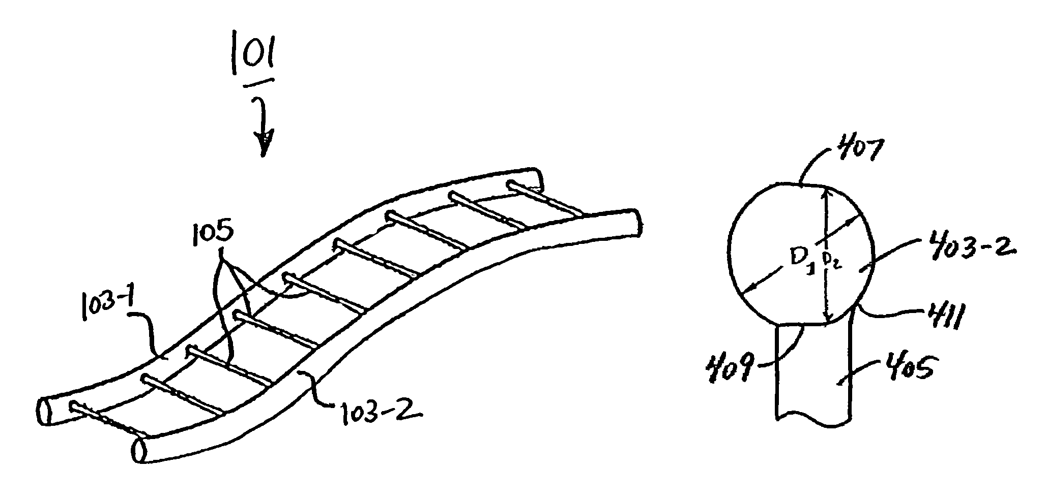
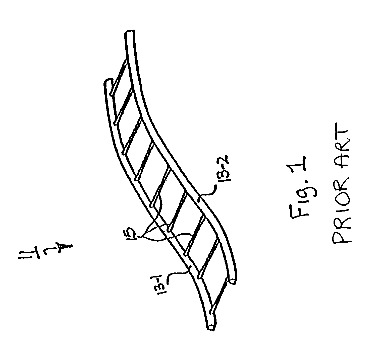
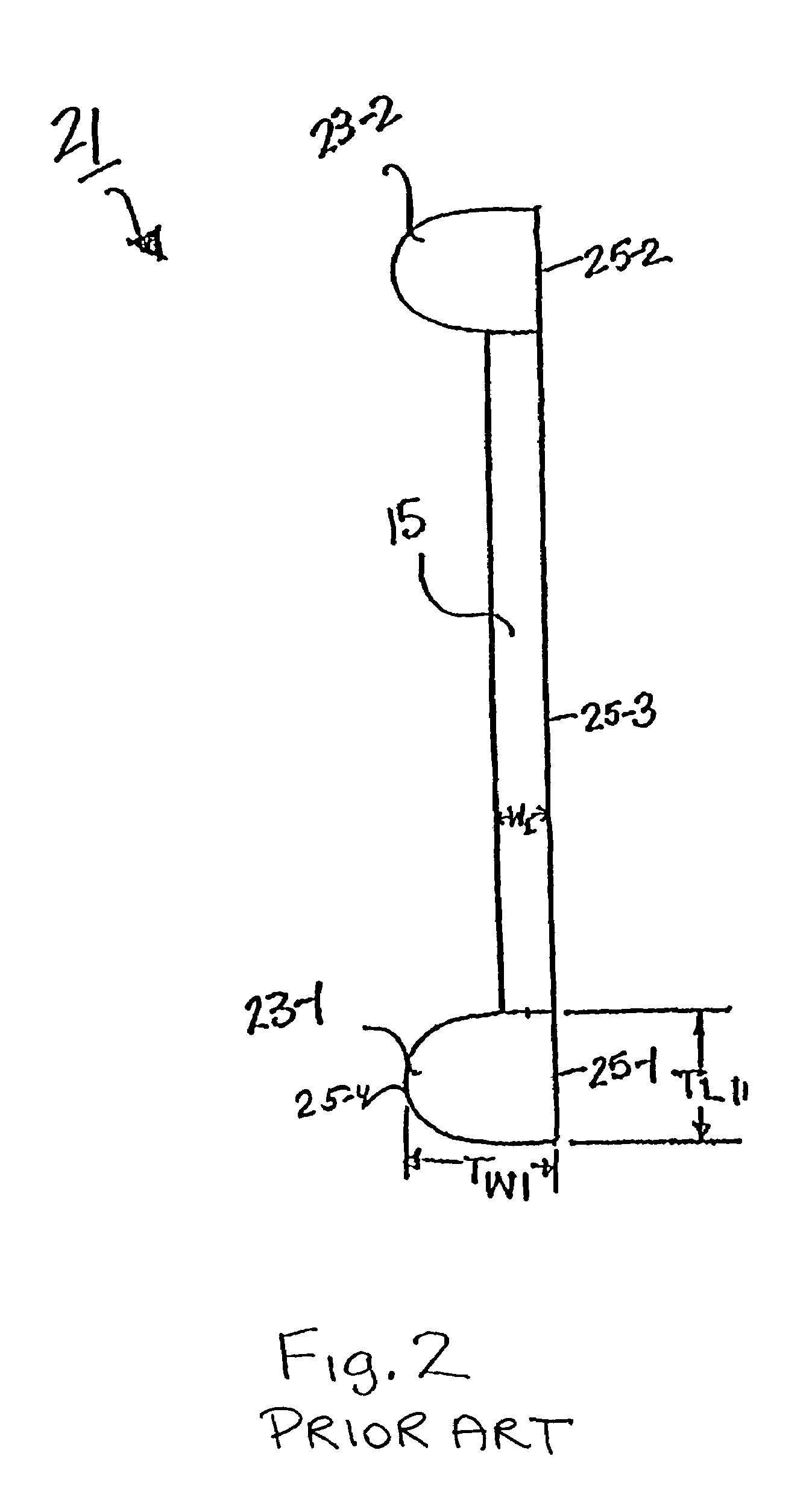
Continuously connected fastener stock and method of manufacturing the same
a technology of continuous connection and fastener stock, which is applied in the field of plastic fasteners, can solve the problems of large unused space within the needle, and large unused space, and achieve the effect of reducing the transverse cross-sectional size of the needl
- Summary
- Abstract
- Description
- Claims
- Application Information
AI Technical Summary
Benefits of technology
Problems solved by technology
Method used
Image

Examples
second embodiment
[0075]Referring now to FIGS. 11(a) and 11(b), there are shown side and perspective views, respectively, of a skiving knife constructed according to the teachings of the present invention, said skiving knife being represented generally by reference numeral 201.
[0076]As seen best in FIG. 11(b), skiving knife 201 is similar in many respects to skiving knife 111, the principal difference between the two knives being that skiving knife 201 is provided with a bottom edge 203 having a pair of rectangular cut-away portions 205-1 and 205-2, as compared to the arcuate cut-away portions 115-1 and 115-2 of knife 111. Knife 201 is adapted for, but is not limited to, use in combination with a modified molding wheel whose side member impressions are rectangular, as opposed to semi-elliptical, in transverse cross-section and whose cross-link impressions include a rounded surface. An example of a length of plastic staple stock fabricated using knife 201 and a molding wheel as described above is show...
fourth embodiment
[0084]Referring now to FIG. 16, there is shown an end view of a length of continuously connected fastener stock of the plastic staple variety that has been fabricated in accordance with the teachings of the present invention, said length of fastener stock being represented generally by reference numeral 301.
[0085]Fastener stock 301 is similar to fastener stock 101 in that fastener stock 301 comprises a pair of elongated, uniform and continuous side members 303-1 and 303-2 that are coupled together by a plurality of flexible cross-links 305 that are equidistantly-spaced apart. Preferably, cross-links 305 are spaced apart by a distance of 0.18 inch. Fastener stock 301 like stock 101 is preferably constructed of urethane.
[0086]An individual plastic fastener 302 that has been cut from fastener stock 301 is shown separately in FIG. 17 and can be seen to include a pair of cross-bars 304-1 and 304-2 interconnected by a cross-link 305. As can be appreciated cross-bars 304-1 and 304-2 have a...
PUM
| Property | Measurement | Unit |
|---|---|---|
| distance | aaaaa | aaaaa |
| length | aaaaa | aaaaa |
| width w1 | aaaaa | aaaaa |
Abstract
Description
Claims
Application Information