Flashlight

a technology of flashing light and flashing plate, which is applied in the field of flashing plate, can solve the problems of inefficient incandescent bulbs, inconvenient use, and fragile incandescent bulbs, and achieve the effect of maximizing the surface area contact and maximizing the mass of conductive materials

Inactive Publication Date: 2007-12-18
LIGHTSTICK PARTNERS
View PDF6 Cites 12 Cited by
  • Summary
  • Abstract
  • Description
  • Claims
  • Application Information

AI Technical Summary

Benefits of technology

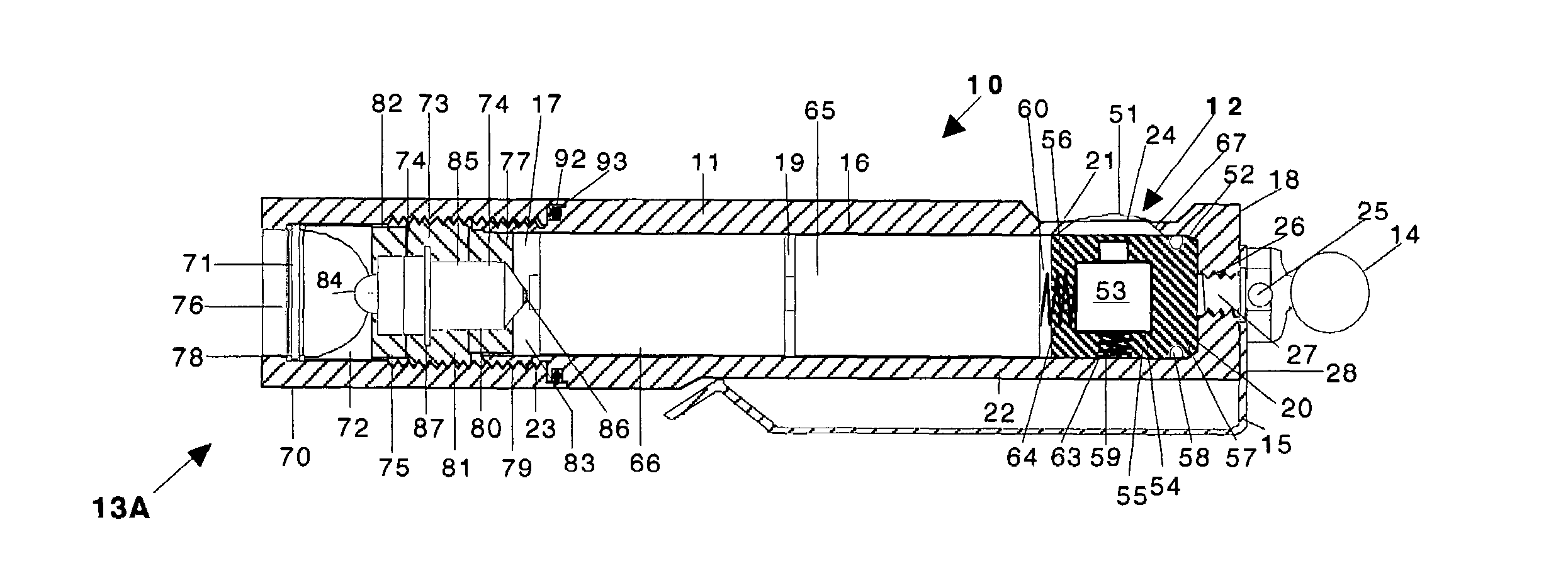
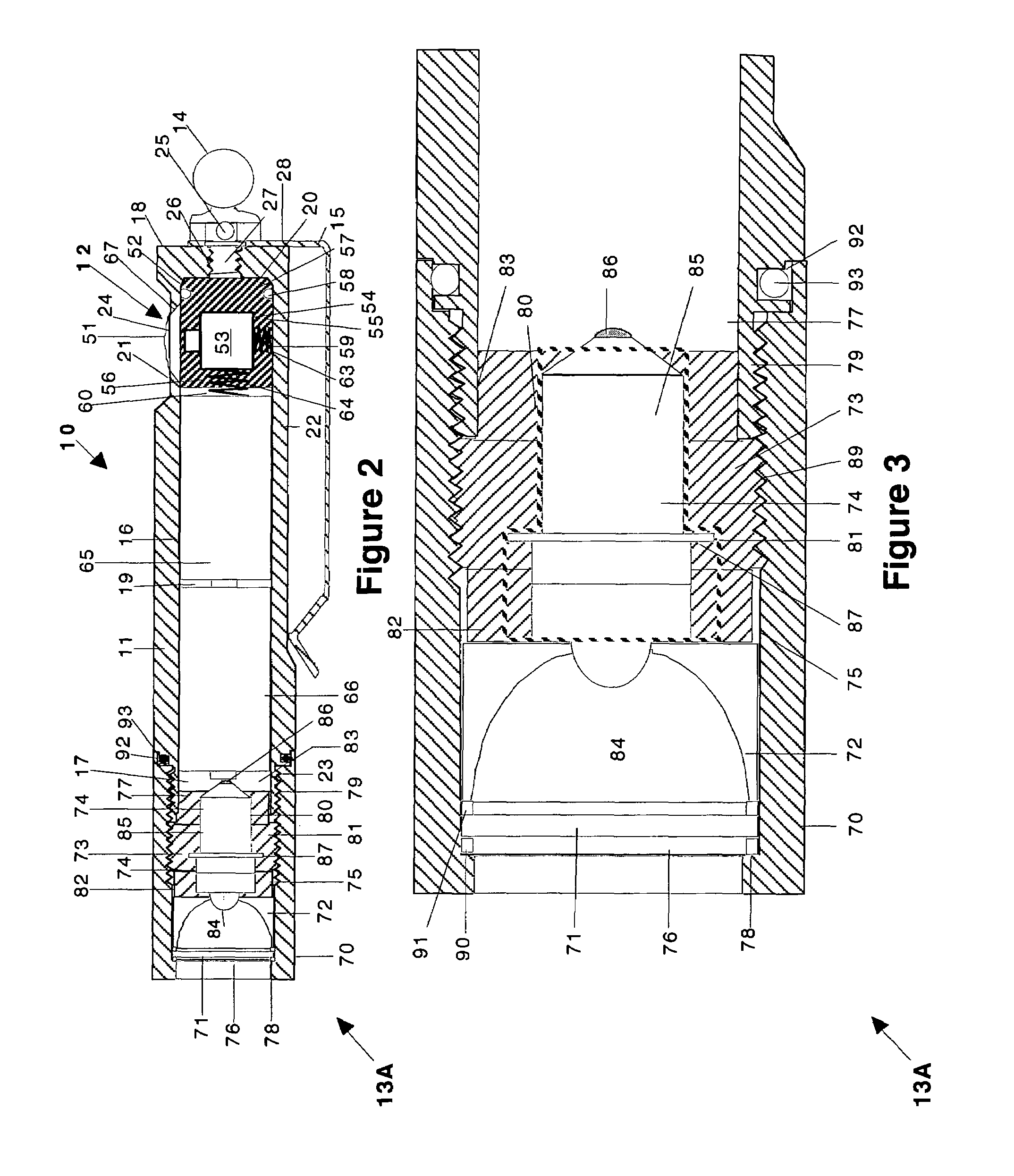
[0009]The flashlight head assembly includes a first end and a second end securable to the body, a lens disposed in the flashlight head at the first end, a reflector disposed in the flashlight head adjacent the lens, a heat sink disposed in the flashlight head adjacent the reflector, and an LED assembly disposed within the heat sink such that the heat sink substantially completely surrounds the LED assembly. The heat sink substantially completely surrounds the LED assembly in order to maximize the surface area contact between the heat sink and the LED assembly. The heat sink further substantially completely surrounds the LED assembly in order to maximize the mass of conductive material about the LED assembly. The heat sink engages the flashlight head such that the flashlight head assembly functions as a heat sink for the LED assembly. Similarly, the flashlight head assembly engages the body such that the flashlight functions as a heat sink for the LED assembly. The reflector may be constructed from a thermally conductive material such that, when the heat sink engages the reflector, the reflector functions as a heat sink for the LED assembly.

Problems solved by technology

Incandescent bulbs operate adequately; nevertheless, such bulbs suffer certain disadvantages.
Incandescent bulbs are fragile and often break when a flashlight is jarred.
Incandescent bulbs further are inefficient in that batteries utilized to supply power are typically drained after less than an hour of continuous use.
Incandescent bulbs still further allow leakage from the batteries such that the batteries are drained even when a flashlight is off.

Method used


Image

  • Flashlight
  • Flashlight
  • Flashlight

Examples


first embodiment

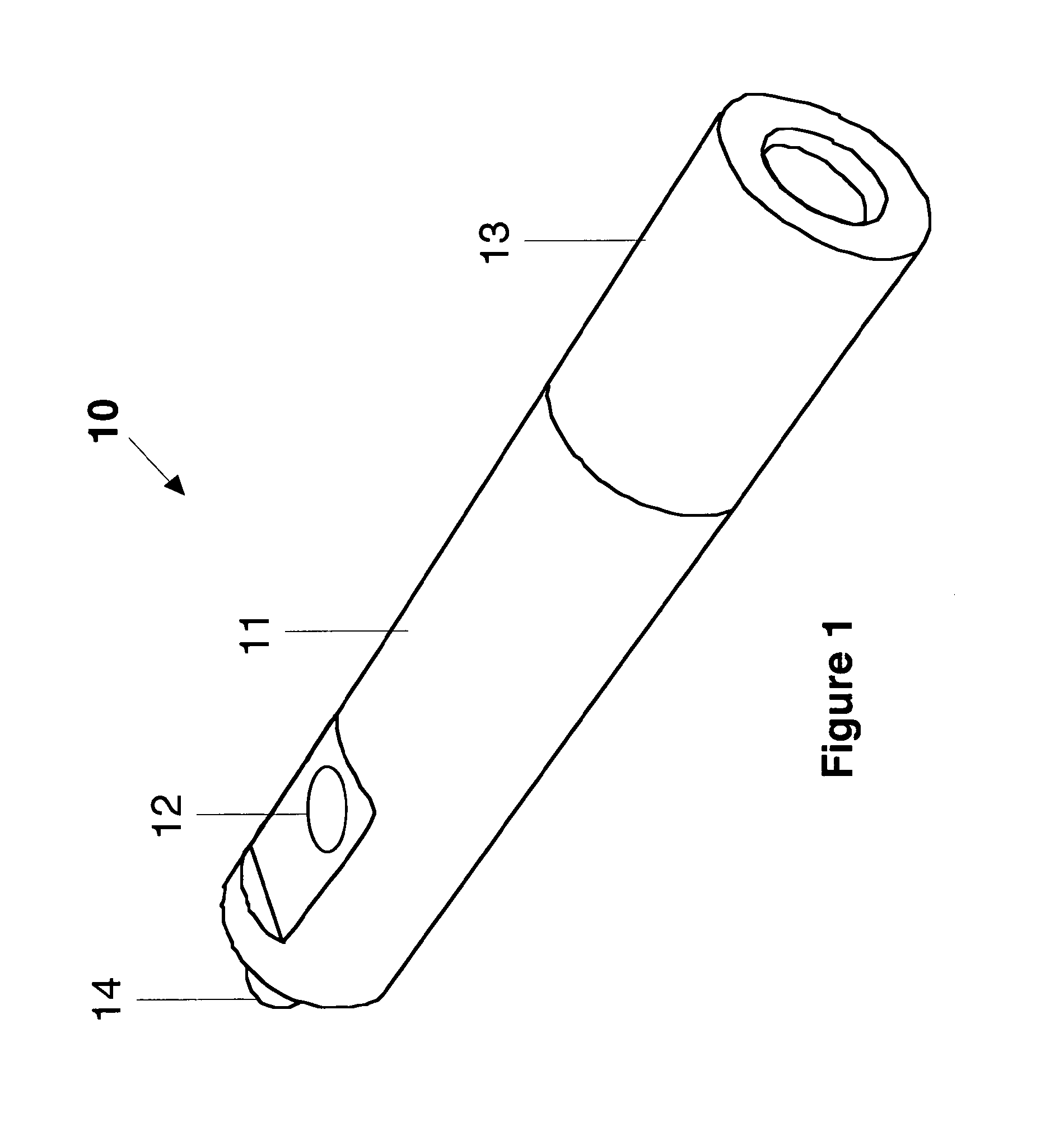
[0050]Referring to FIGS. 1, 2, and 4, the body 11 includes a bore 16 that begins at a first open end 17 of the body 11 and ends at a second closed end 18 of the body 11. The bore 16 provides the body 11 with a battery compartment 19 and a switch assembly compartment 20. The battery compartment 19 in the flashlight 10 is adapted to receive two batteries. While the flashlight 10 includes two batteries, those of ordinary skill in the art will recognize that the length of the body 11 may be increased to receive additional batteries. The first end 17 of the body 11 includes threads 23 that facilitate securing of the flashlight head assembly 13 onto the body 11 in a position aligned with the axis of the body 11. The first end 17 of the body 11 further includes a groove 92 that receives an o-ring 93 therein. The o-ring 93 provides a fluid tight seal between the body 11 and the flashlight head assembly 13. The body 11 further includes a base 21 and a switch aperture 24 at the base 21. The b...

second embodiment

[0065]Referring to FIGS. 11-15, a flashlight head assembly 13B includes a flashlight head 170, a lens 171, a reflector 172, a heat sink 173, and an LED assembly 174. The flashlight head 170 includes a bore 175 therethrough beginning at a first end 176 and ending at a second end 177. The flashlight head 170 at the first end 176 includes a lip 178 that provides a surface for retaining the lens 171 within the flashlight head 170. The flashlight head 170 at the second end 176 includes threads 179 internal thereto that maintain the heat sink 173 within the flashlight head 170 as well as facilitate the securing of the flashlight head assembly 13B onto the body 11.

[0066]The LED assembly 174 is available from LED Dynamics, Inc., whose business address is 44 Hull Street, Randolph, Vt. 05060. The LED assembly 174 includes a printed circuit board 185, an LED 184 mounted onto the printed circuit board 185, and a micro-electronic circuit 194 mounted onto the printed circuit board 185 wherein th...

third embodiment

[0071]Referring to FIGS. 16-23, a flashlight head assembly 13C includes a flashlight head 270, a lens 271, a reflector 272, a heat sink 273, and an LED assembly 274. The flashlight head 270 includes a bore 275 therethrough beginning at a first end 276 and ending at a second end 277. The flashlight head 270 at the first end 276 includes a lip 278 that provides a surface for retaining the lens 271 within the flashlight head 270. The flashlight head 270 at the second end 276 includes threads 279 internal thereto that maintain the heat sink 273 within the flashlight head 270 as well as facilitate the securing of the flashlight head assembly 13C onto the body 11.

[0072]The LED assembly 274 is available from LED Dynamics, Inc., whose business address is 44 Hull Street, Randolph, Vt. 05060. The LED assembly 274 includes a printed circuit board 285, an LED 284 electrically coupled with the printed circuit board 285 via an input lead 286 and a ground lead 295 of the LED 284, and a micro-elec...


PUM


Abstract

A flashlight includes a body, a flashlight head assembly, and a switch assembly. The body includes a first end securable to the flashlight head assembly, a second end, and a substantially cylindrical portion between the first end and the second end. The switch assembly, which is located at the substantially cylindrical portion of the body adjacent the second end, electrically connects with the flashlight head assembly to regulate the delivery of power thereto. The flashlight head assembly includes a first end and a second end securable to the body, a lens disposed in the flashlight head at the first end, a reflector disposed in the flashlight head adjacent the lens, a heat sink disposed in the flashlight head adjacent the reflector, and an LED assembly disposed within the heat sink such that the heat sink substantially completely surrounds the LED assembly. The flashlight further includes a clip disposed at the second end of the body and a hitch ball securable to the second end of the body such that the hitch ball fastens the clip to the body. The flashlight may further include a baton securable to the second end of the body.

Description

CROSS-REFERENCE TO RELATED APPLICATION[0001]This present application claims all available benefit, under 35 U.S.C. § 119(e), of U.S. provisional patent application Ser. No. 60 / 630,455 filed Nov. 23, 2004. By this reference, the full disclosure of U.S. provisional patent application Ser. No. 60 / 630,455 is incorporated herein as though now set forth in its entirety.BACKGROUND OF THE INVENTION[0002]1. Field of the Invention[0003]The present invention relates to flashlights and, more particularly, but not by way of limitation, to a flashlight incorporating light emitting diode (LED) technology.[0004]2. Description of the Related Art[0005]The majority of flashlights currently marketed employ an incandescent bulb to supply the light beam. Incandescent bulbs operate adequately; nevertheless, such bulbs suffer certain disadvantages. Incandescent bulbs are fragile and often break when a flashlight is jarred. Incandescent bulbs further are inefficient in that batteries utilized to supply powe...

Claims


Application Information

Patent Timeline
Patent Type & Authority Patents(United States)
IPC IPC(8): F21V29/00
CPCF21L4/027F21V23/0414F21V29/20F21V29/004F21Y2101/02F21Y2115/10F21V29/70
Inventor MARTIN, RICHARD W.
Owner LIGHTSTICK PARTNERS
Why Eureka
Try Eureka