Use of high modulus, impact resistant foams for structural components

Inactive Publication Date: 2005-04-26
GENERAL ELECTRIC CO
View PDF17 Cites 29 Cited by
  • Summary
  • Abstract
  • Description
  • Claims
  • Application Information

AI Technical Summary

Benefits of technology

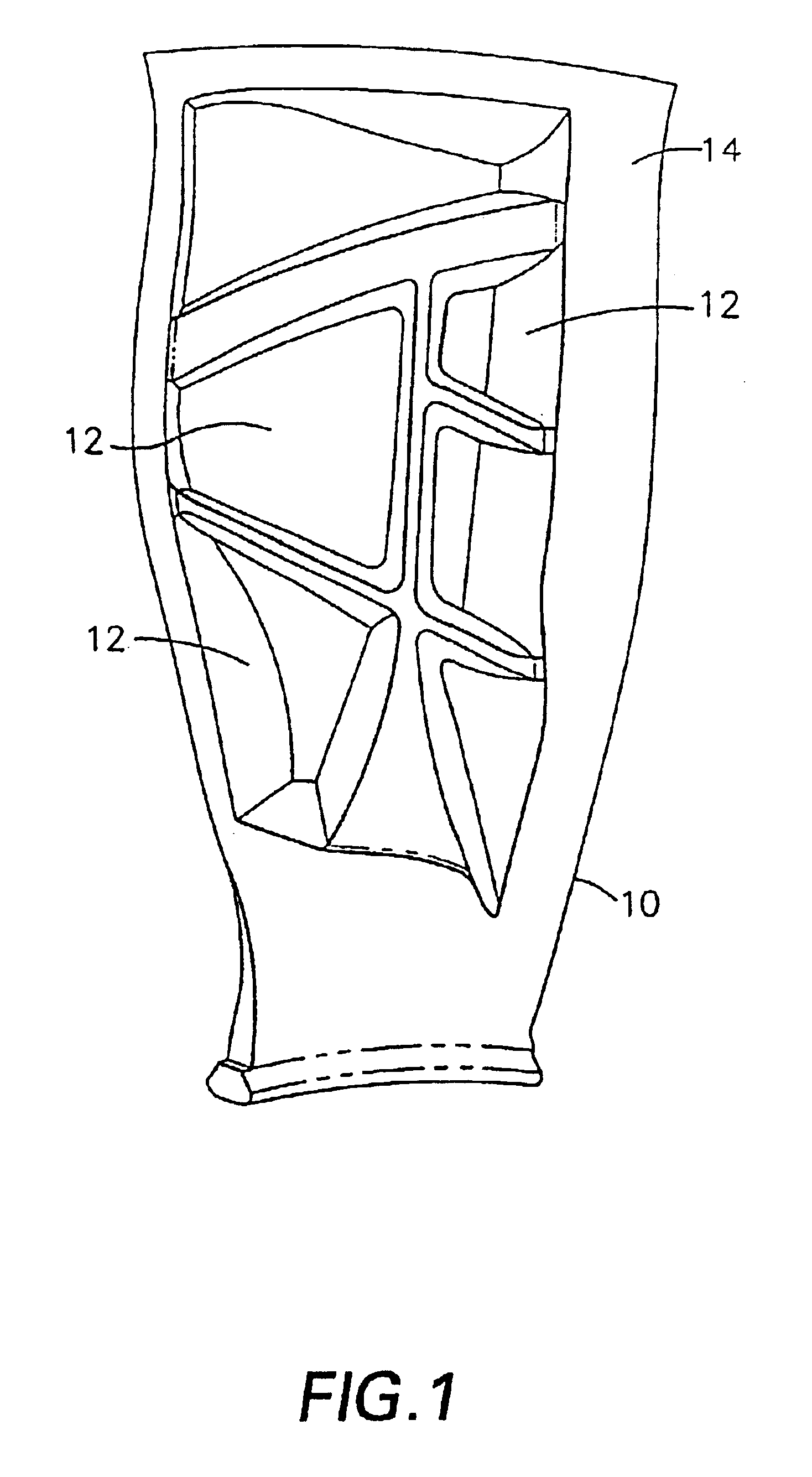
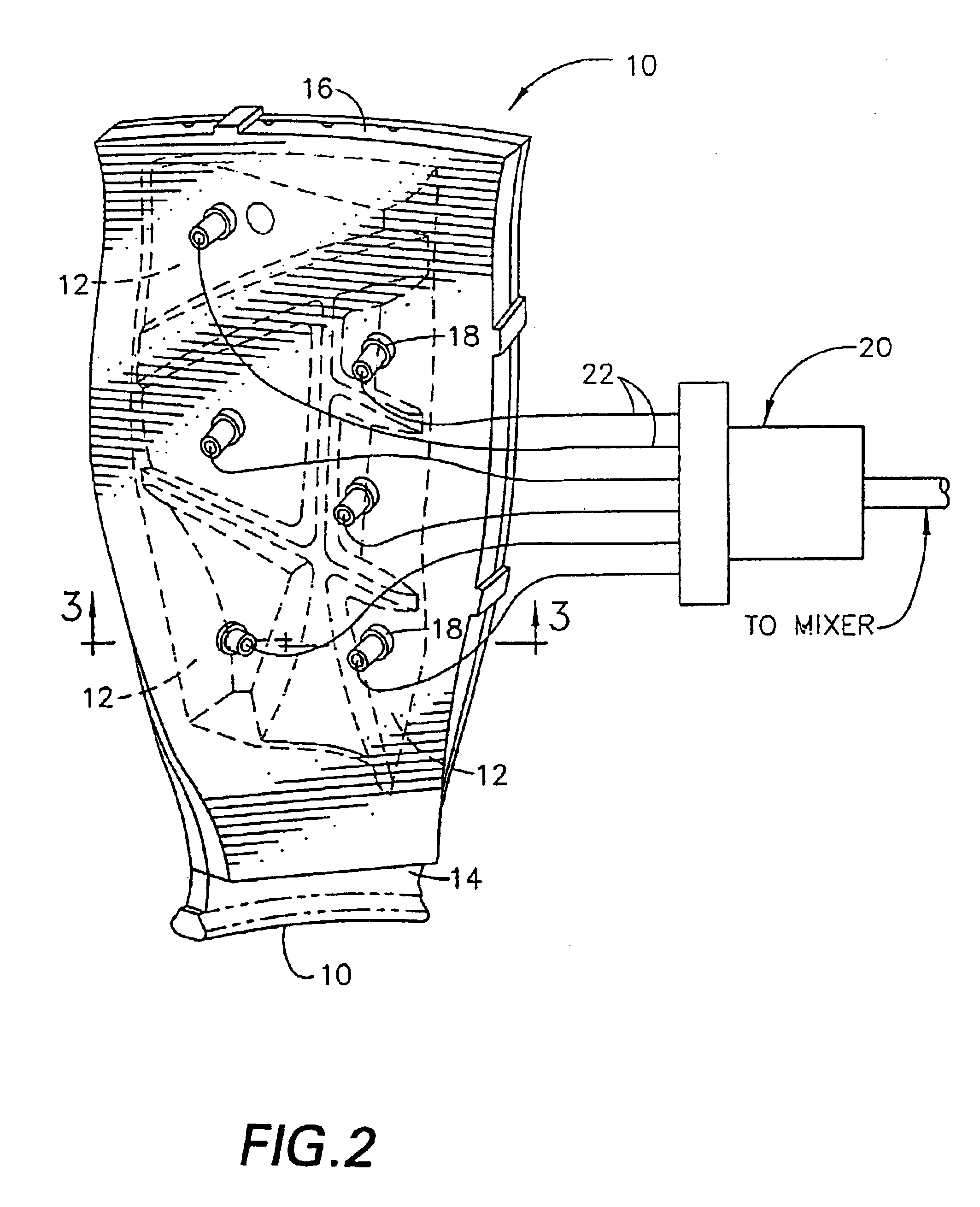
[0042]One advantage of the present invention is that the elastomeric polyurethane composition can be cured directly to the blade. Because the pockets form part of the mold, the foam mates with essentially 100% of the available interface surface area of the blade. Because of the excellent adhesive characteristics of the polyurethane to the metal, the maximization of the surface area contact between the polyurethane and the metal provides for a strongly bonded insert.
[0043]Alternatively, a chemical bonding agent can be utilized to enhance the adhesion of the polyurethane to the metal, or the pockets of the blade may be roughened so that the surface area on the metal or composite blade is increased, thereby increasing the mechanical strength of the bond between the metal or composite blade and the thermoset composition.
[0044]In this regard, one type of chemical bonding agent that can be utilized is THIXON®, a vulcanizable film formed by elevated temperature crosslinking, and commercially available from Morton International. Another and preferred type of chemical bonding agent is a chemical mixture of solvents that act as a carrier for at least one filler and dissolved phenolic resins derived from substituted phenols, including but not limited to phenol, o-cresol, p-cresol, 2,6-xylenol, 2,4-xylenol, alkyl phenol, and t-butylphenol. Other equivalent variations of these chemical species may be substituted or additionally included in the mixture. The carriers and solvents will evaporate, leaving the filler and phenolic resins that will provide an adhesive bond with the blade and the elastomeric composition. Preferred sol

Problems solved by technology

Control of the void spaces in such systems is thus difficult and there exists a va

Method used


Image

  • Use of high modulus, impact resistant foams for structural components
  • Use of high modulus, impact resistant foams for structural components
  • Use of high modulus, impact resistant foams for structural components

Examples


example 1

[0051]ADIPRENE® LF950A (7,660 grams) polyurethane prepolymer (Uniroyal) (5.93% NCO content) was weighed into a large metal pail, and placed in an oven preheated to 150° F. Powdered LONZACURE® MCDEA (1,000 grams) was weighed into a separate 1 gallon metal can. To the dry LONZACURE® MCDEA was added IRGANOX® 5057 (0.094 grams), TINUVIN® 571 (0.94 grams), and TINUVIN® 765 (0.188 grams). The 1 gallon can containing the LONZACURE-IRGANOX-TINUVIN mixture was then placed in an oven preheated to 225° F. When the LONZACURE-IRGANOX-TINUVIN mixture was completely melted, it was stirred with a metal paint stirrer to ensure uniformity and then filtered through a strainer into the “curative tank” of a standard, multi-tank polyurethane processing apparatus. The curative tank and associated transfer lines were preheated to 225° F. An atmosphere of dry nitrogen at 35 psi was maintained in the curative tank.

[0052]The ADIPRENE® LF950A® prepolymer, now heated to 150° F., was removed from the oven and wh...


PUM

PropertyMeasurementUnit
Lengthaaaaaaaaaa
Fractionaaaaaaaaaa
Fractionaaaaaaaaaa

Abstract

The present invention provides tough, high modulus, low density thermoset polyurethane compositions which are useful in general as, for example, cast structural materials and in a preferred embodiment can be cured directly onto an aircraft engine fan blade, thereby providing a lighter blade, without concomitant loss in structural integrity or blade performance due to, for example, resistance to foreign object impacts and fuel efficiency. In a preferred embodiment, the composition is comprised of bis-amine compounds reacted with isocyanate-functional polyether polymers in the presence of hollow polymeric microspheres. The thermoset polymer compositions are formed by casting into a mold which is formed by a cavity within the metallic or composite fan blade or guide vane in the form of a pocket and a removable caul sheet. After the elastomeric polyurethane foam is injected through at least one injector port into the mold, the foam is cured.

Description

RELATED APPLICATION[0001]This application is a continuation-in-part of U.S. application Ser. No. 09 / 682,684, filed Oct. 5, 2001 now abandoned.BACKGROUND OF THE INVENTION[0002]The present invention relates generally to thermoset polymeric compositions useful in structural applications, and more particularly to turbine blades comprised of two or more components made from different materials, one of which is the thermoset polymeric compositions of the invention.[0003]Turbines include, but are not limited to, gas and steam turbine power generation equipment and gas turbine aircraft engines. A gas turbine includes a core engine having a high pressure compressor to compress the air flow entering the core engine, a combustor in which a mixture of fuel and compressed air is burned to generate a propulsive gas flow, and a high pressure turbine which is rotated by the propulsive gas flow and which is connected by a larger diameter shaft to drive the high pressure compressor. A typical front f...

Claims


Application Information

Patent Timeline
IPC IPC(8): C08G18/00C08J9/00C08J9/32C08G18/10B29D99/00F01D5/14
CPCC08G18/10C08J9/32F01D5/28F01D5/147C08G18/3814C08G2101/00C08J2203/22C08J2375/04Y10T428/2985Y02T50/672Y02T50/673Y02T50/60
Inventor LIN, WENDY WEN-LINGFINN, SCOTT ROGERFLANAGAN, KEVIN WARNERSTEVENSON, JOSEPH TIMOTHYCARNAHAN, JAMES CLAUDE
Owner GENERAL ELECTRIC CO
Why Eureka
Try Eureka