Down-the-hole hammer drill bit retaining assembly

a drill bit and assembly technology, applied in drilling drives, sealing/packing, borehole/well accessories, etc., can solve the problems of weakened conventional bit retainers, compromised drill bit retention, disadvantages of conventional retaining assemblies, etc., and achieve strong and reliable retention of drill bits.

Active Publication Date: 2020-05-26
SANDVIK INTELLECTUAL PROPERTY AB
View PDF21 Cites 1 Cited by
  • Summary
  • Abstract
  • Description
  • Claims
  • Application Information

AI Technical Summary

Benefits of technology

[0007]It is an objective of the present invention to provide percussive drill apparatus and in particular a drill bit retaining assembly that is configured to maintain strong and reliable retention of the drill bit when required whilst enabling delivery of a desired volume of a lubricant containing fluid to the radially outer region of the drill bit and in contact with the rotational drive splines projecting radially inward from the drive sub.
[0008]It is a further specific objective to provide a retaining assembly compatible with existing drill bits and a piston hammer arrangement specifically with regard to the radial and axial dimensions of such arrangements and components and hence does not require changes to existing percussive drilling apparatus.
[0009]The objectives are achieved by providing a down-the-hole hammer drill bit retaining assembly comprising drive sub and retainer ring configured specifically to allow a fluid flow pathway over a radially external facing surface of the retainer ring and then into contact with a radially inward facing surface of the drive sub and importantly the drive sub splines. Accordingly, the radially inner region of the retainer ring is configured and optimised for abutment contact with the axially rearward shoulder projecting from the bit shaft and in particular to maximise the surface area contact with the shoulder when the retainer ring is required to retain the drill bit at the hammer assembly between drilling / hammering intervals. Accordingly, the present retainer ring and drill bit retaining assembly provides a dual function of retaining the drill bit securely and reliably in addition to defining a desired fluid flow pathway into the region of the drive sub splines with this passageway extending exclusively or predominantly over the radially outer surface or region of the retainer ring.
[0014]Preferably, the retainer ring and the drive sub are configured such that the drive sub is positionable to axially overlap and to radially encompass at least a part of the retainer ring. Accordingly, the retainer ring comprises an external diameter being less than (but approximately equal to) an internal diameter of the drive sub at its rearward end. Accordingly, the drive sub is configured to encapsulate in close fitting contact at least an axially forward region of the retainer ring. Such a configuration maintains the segments of the retainer ring as an annular assembly in mounted position over the drill bit shaft. This is advantageous to obviate the need for any additional retaining gasket.
[0017]Optionally, the drive sub may comprise an annular shoulder provided at or towards the rearward end to mate with the retainer ring. Optionally, the retainer ring may comprise an annular shoulder to mate with the annular shoulder of the drive sub. Such a configuration is advantageous to enhance the axial and radial connection of the drive sub and the retainer ring as a unified assembly within the hammer arrangement.

Problems solved by technology

However, these conventional retaining assemblies are disadvantageous for a number of reasons.
Accordingly, conventional bit retainers are weakened and drill bit retention is compromised.

Method used


Image

  • Down-the-hole hammer drill bit retaining assembly
  • Down-the-hole hammer drill bit retaining assembly
  • Down-the-hole hammer drill bit retaining assembly

Examples


second embodiment

[0050]According to the embodiment of FIGS. 5 to 7, split ring 126 comprises a shoulder 146 extending from axially forward annular face 152. The radially outward facing ring shoulder 146 is configured to mate with the complementary radially inward facing annular drive sub shoulder 168. Accordingly, ring 126 via the shoulders 146, 168 is capable of being interconnected to sit at least partially under the axially rearward end of drive sub 110 to be maintained in the axial and radial position within hammer 100. collar 125 is also configured slightly differently to the embodiment of FIGS. 2 to 4 by comprising axially extending grooves (or channels) 144 recessed into the radially inward facing surface 137. Grooves 144 are spaced apart in the circumferential direction around the collar 125 and extend axially from collar rearward end region 136 to collar forward end face 131. Grooves 144 are configured to facilitate axial forward delivery of the fluid along flow pathway 162 and through the...

third embodiment

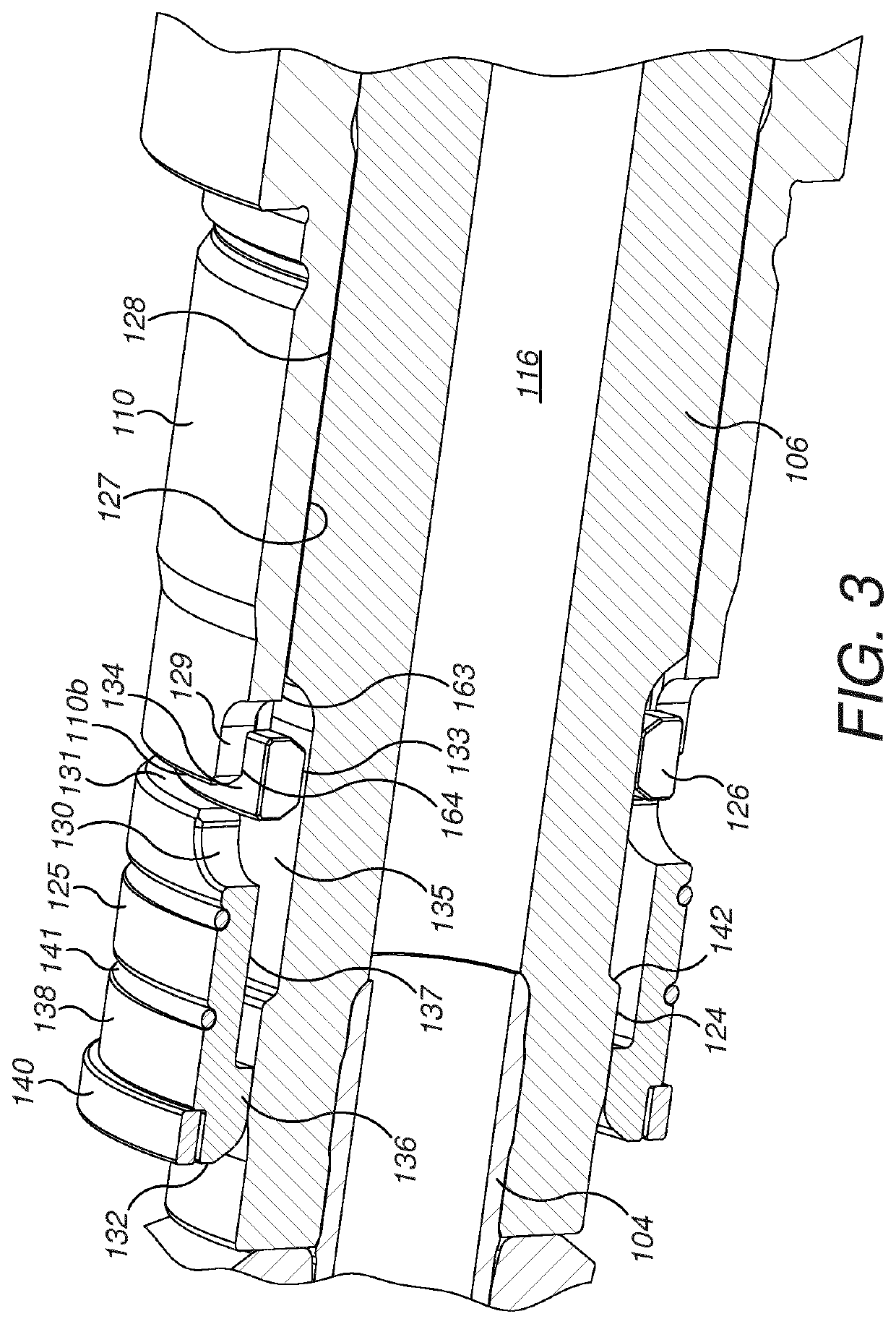
[0052]To provide the openings 153 for the through-flow of the flushing fluid, retainer ring 126 comprises slots 149 extending the full radial thickness of ring 126 and axially into the ring body from rearward facing end face 151. Slots 149 extend to an approximate mid-axial length position between end face 151 and abutment face 150. Each slot 149 is terminated axially by a respective groove 160 recessed into the outward facing ring surface 134. Common to all embodiments described herein, drive sub 110 comprises slots 129 extending axially from rearward end face 110b. A width in a circumferential direction of each ring groove 160 is equal to a corresponding width in a circumferential direction of each drive sub slot 129. Slots 149 and 129, as before, define respective openings 153, 154 between the radially internal and external regions of the retainer assembly 108. retainer ring outward surface 134 is generally co-aligned with the collar outward facing surface 138 and the correspond...


PUM


Abstract

A down-the-hole hammer drill bit retaining assembly is arranged to releasably retain a drill bit at a hammer arrangement of a percussion drilling apparatus. The retaining assembly includes a drive sub and a retainer ring. The drive sub has at least one indent to provide a fluid communication pathway for a flushing fluid extending over a radially outward facing surface of the retainer ring and into an internal region of the drive sub in contact with inwardly projecting splines.

Description

RELATED APPLICATION DATA[0001]This application is a § 371 National Stage Application of PCT International Application No. PCT / EP2017 / 054707 filed Mar. 1, 2017 claiming priority to EP 16158627.6 filed Mar. 4, 2016.FIELD OF INVENTION[0002]The present invention relates to a down-the-hole hammer drill bit retaining assembly to releasably retain a drill bit at a hammer arrangement and in particular, although not exclusively, to a retaining assembly that provides strong and reliable retention of the drill bit.BACKGROUND ART[0003]The technique of down-the-hole (DTH) percussive hammer drilling involves the supply of a pressurised fluid via a drill string to a drill bit located at the bottom of a bore hole. The fluid acts to both drive the hammer drilling action and to flush rearwardly dust and fines resultant from the cutting action, rearwardly through the bore hole so as to optimise forward cutting.[0004]Typically, the drill assembly comprises a casing extending between a top sub and a dri...

Claims


Application Information

Patent Timeline
Patent Type & Authority Patents(United States)
IPC IPC(8): E21B10/36E21B34/06E21B4/14E21B17/07E21B6/02E21B44/00
CPCE21B10/36E21B34/06E21B17/076E21B4/145E21B6/02E21B44/005E21B17/07E21B4/14
Inventor BRUANDET, OLIVIER
Owner SANDVIK INTELLECTUAL PROPERTY AB
Why Eureka
Try Eureka