Beverage bottle cooling method and apparatus with assembly for holding ice and water

a technology for ice and water bottles and cooling methods, which is applied in the field of beverage coolers, can solve the problems of cumbersome use, two liter and other large-scale sizes are susceptible to the same, and the beverage becomes hot quickly

Inactive Publication Date: 2005-06-16
SHIMAZAKI J JOHN
View PDF44 Cites 10 Cited by
  • Summary
  • Abstract
  • Description
  • Claims
  • Application Information

AI Technical Summary

Benefits of technology

[0010] The cooler is preferably adapted to securely hold a particular beverage bottle, such as a PET bottle having a certain size and shape. The cooler is preferably sized and shaped so that a particular bottle can be held inside, with a sealed compartment surrounding the bottle, wherein regular ice cubes can be stored and sealed within the compartment to substantially surround the bottle. This way, ice can be maintained in direct contact with the bottle, and the beverage can be maintained at a reduced temperature, without diluting or introducing contaminants into the beverage. The beverage can also easily be poured, served and consumed without having to take the bottle out of the ice.
[0015] The container, including the support(s), is preferably integrally formed with substantially uniform wall thickness, which can be made by conventional molding methods. One preferred goal of the present invention is to substantially minimize the surface area contact between the container and bottle, on one hand, and substantially maximize the surface area contact between the ice and bottle, on the other hand, and the above construction preferably helps to accomplish this goal.
[0018] Another aspect of the present invention is that the cooler can be specifically made to accommodate a certain type of beverage bottle, while not accommodating other beverage bottles, such as those having different sizes and shapes. PET bottles often come in a variety of different sizes and shapes, even with bottles having the same volume. Nevertheless, another aspect of the present invention is that a single cooler can be designed to fit more than one bottle type, such as bottles with slightly different sizes and shapes, which can be accomplished by locating and configuring the sealing member in a manner that achieves a watertight seal, despite differences in size and shape.

Problems solved by technology

In either case, when the weather is warm, or on a hot sunny day, exposure to high temperatures can result in the beverage becoming warmer quickly, without any means of keeping the beverage cold.
Two liter and other larger sizes are susceptible to the same results, such as during an outdoor picnic, or other function, where no refrigerator is available to keep the beverage cold.
In the past, resort has been made to using ice chests, but there are disadvantages to doing so.
For example, because PET bottles are often large, larger ice chests are typically needed, in which case they can be cumbersome to use.
Moreover, it is burdensome to use an ice chest if only a single serving bottle needs to be kept cold.
Also, when two liter or other larger bottle sizes are involved, it is often impractical to keep them in ice chests while the beverage is being served.
The disadvantage of this, however, is that as ice melts, the beverage can become diluted.
Carbonation can also dissipate quickly.
For example, in U.S. Pat. Nos. 81,814; 592,781 and 303,815, wine bottle coolers, such as with diaphragms and springs to hold bottles in place are shown, but these designs were not compact, not easy to manufacture, nor suitable for bottles with twist off lids, since the bottles were free to rotate.
In later years, as shown in U.S. Pat. Nos. 3,998,072, 4,281,520, 5,555,746 and 5,904,267, containers with various compartments, sleeves and packs filled with refrigerants were developed, but these required the refrigerant to be frozen and refrozen after each use, and therefore, were not convenient to use.

Method used


Image

  • Beverage bottle cooling method and apparatus with assembly for holding ice and water
  • Beverage bottle cooling method and apparatus with assembly for holding ice and water
  • Beverage bottle cooling method and apparatus with assembly for holding ice and water

Examples


Embodiment Construction

[0040] Several embodiments of the invention are described and shown.

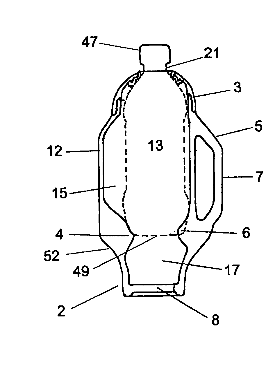
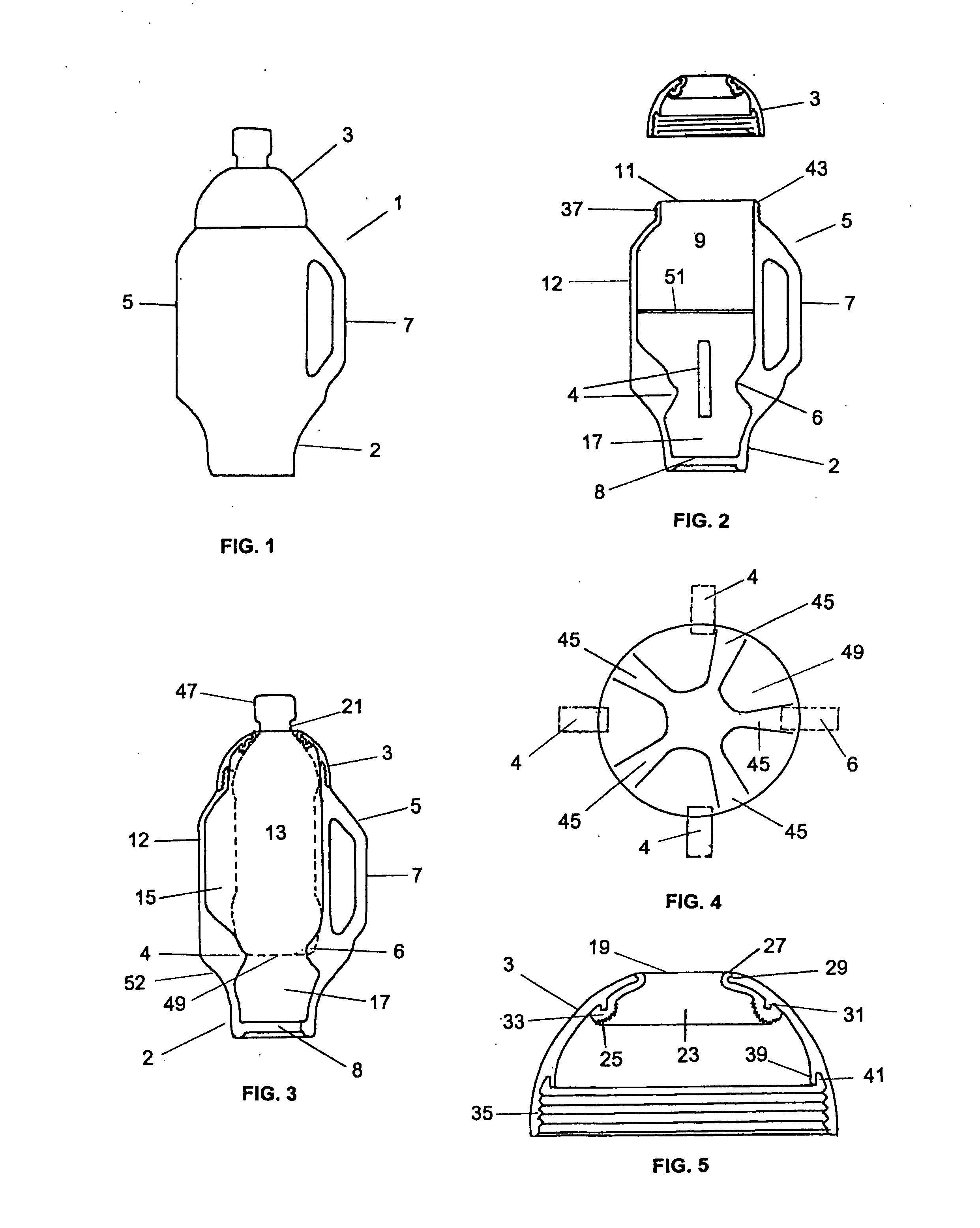
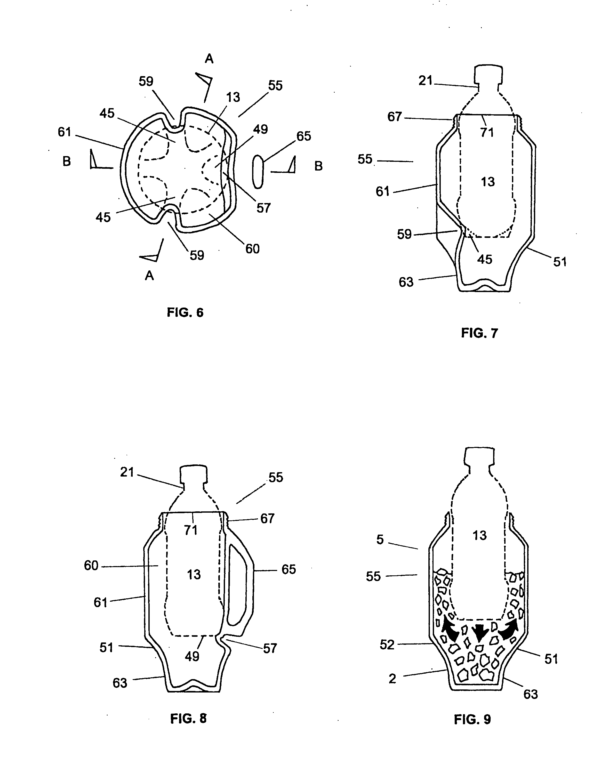
[0041]FIGS. 1-3 show a first embodiment of the present invention 1 having a container 5 and cap 3 designed to be connected and sealed together. As seen in FIGS. 2-3, container 5 is preferably an open-top container having a handle 7 and an internal space 9 formed by a wall 12, much like a large mug, wherein an opening on the top 11 enables a bottle 13, such as a commercial PET bottle, to be inserted therein. Container 5 preferably has extended on the inside thereof a plurality of supports 4, 6, such as extending inward from wall 12, which are adapted to provide lateral and vertical support to bottle 13. This way, bottle 13 can be inserted into container 5, and supported by supports 4, 6, in a substantially fixed location, wherein spaces 15, 17, shown in FIG. 3, can be formed between bottle 13 and wall 12 of container 5 for storing ice and water therein.

[0042] All or a portion of wall 12 can be cylindrical or any sh...


PUM


Abstract

The present invention relates to a beverage bottle cooling apparatus and method comprising a container for containing ice that is adapted to have a commercial beverage bottle positioned substantially therein, wherein regular ice cubes can be stored and sealed within the space between the bottle and container. The space is preferably substantially sealed by a cap which is adapted with an opening and sealing member that extends over the neck of the bottle, wherein the bottle can be held in a predetermined location by one or more supports extended within the container. The container, including the supports, is preferably molded and formed with substantially uniform wall thickness, and adapted to fit in conventional cup-holders.

Description

RELATED APPLICATIONS [0001] This application claims priority from co-pending U.S. patent application Ser. No. 10 / 382,526, filed on Mar. 7, 2003, which claims priority from U.S. patent application Ser. No. 10 / 298,613, filed on Nov. 19, 2002, which claims priority from U.S. patent application Ser. No. 10 / 066,656, filed on Feb. 6, 2002, which issued as U.S. Pat. No. 6,588,621 on Jul. 8, 2003, which claims priority from U.S. patent application Ser. No. 09 / 983,107, filed on Oct. 23, 2001, now abandoned. This application also claims priority from U.S. Provisional Patent Application Ser. No. 60 / 528,921, filed on Dec. 11, 2003. Each of the above applications is incorporated herein by reference in its entirety.FIELD OF THE INVENTION [0002] The present invention relates to the field of beverage coolers, and in particular, to a beverage cooling method and apparatus with an assembly for holding ice and water. BACKGROUND OF THE INVENTION [0003] Commercial beverages, such as soda, juice, fruit dr...

Claims


Application Information

Patent Timeline
IPC IPC(8): F25D3/08F25D31/00
CPCF25D3/08F25D31/007F25D2303/081F25D2500/02F25D2303/0845F25D2331/803F25D2331/809F25D2303/0843
Inventor SHIMAZAKI, J. JOHN
Owner SHIMAZAKI J JOHN
Why Eureka
Try Eureka