Integrated float raft

a float raft and integrated technology, applied in the direction of floats, special purpose vessels, rafts, etc., can solve the problems of inability to deploy, activate and utilize rafts, significant cost, and the mounting of raft modules on an already existing float system requires significant modification to the aircraft and comes., and achieves the effect of simple installation methods

Active Publication Date: 2007-12-18
AIR CRUISERS
View PDF8 Cites 30 Cited by
  • Summary
  • Abstract
  • Description
  • Claims
  • Application Information

AI Technical Summary

Benefits of technology

[0012]The integrated float-raft system of the invention provides simplified means for mounting inflatable emergency life-rafts at the exterior of a rotorcraft or helicopter. Unlike other external raft designs of the prior art, the integrated float-raft system of the invention provides the ability to mount the inflatable rafts directly onto the exterior of the inflatable floats. The inflatable floats and rafts are installed on aircraft as independent components and utilize simple installation methods. During deployment of the inflatable float, the raft module remains separated from the float unit and is attached to the float unit by means of a retention arrangement, such as retention straps, adhesives, etc. After the floats are inflated, the rafts can be deployed using a separate activation means. Following activation, the rafts are expelled from the raft modules.
[0013]Unlike known prior art arrangements which pack both the deflated floats and deflated rafts inside a single cover, the integrated float-raft system of the invention uses a raft module which is distinctly independent of the float unit. The essential advantage to the integrated float-raft system of the invention is that the inflatable floats and rafts operate as separate entities. Additionally, the integrated float-raft system of the invention is easily adaptable to the existing and already certified inflatable floatation arrangements.

Problems solved by technology

In the prior art system, failure to activate or deploy the float would cause an inability to deploy, activate, and utilize the raft.
Furthermore, in the prior art, mounting of the raft module on an already existing float system requires significant modification to the aircraft and comes with significant expense.

Method used


Image

  • Integrated float raft
  • Integrated float raft
  • Integrated float raft

Examples


Embodiment Construction

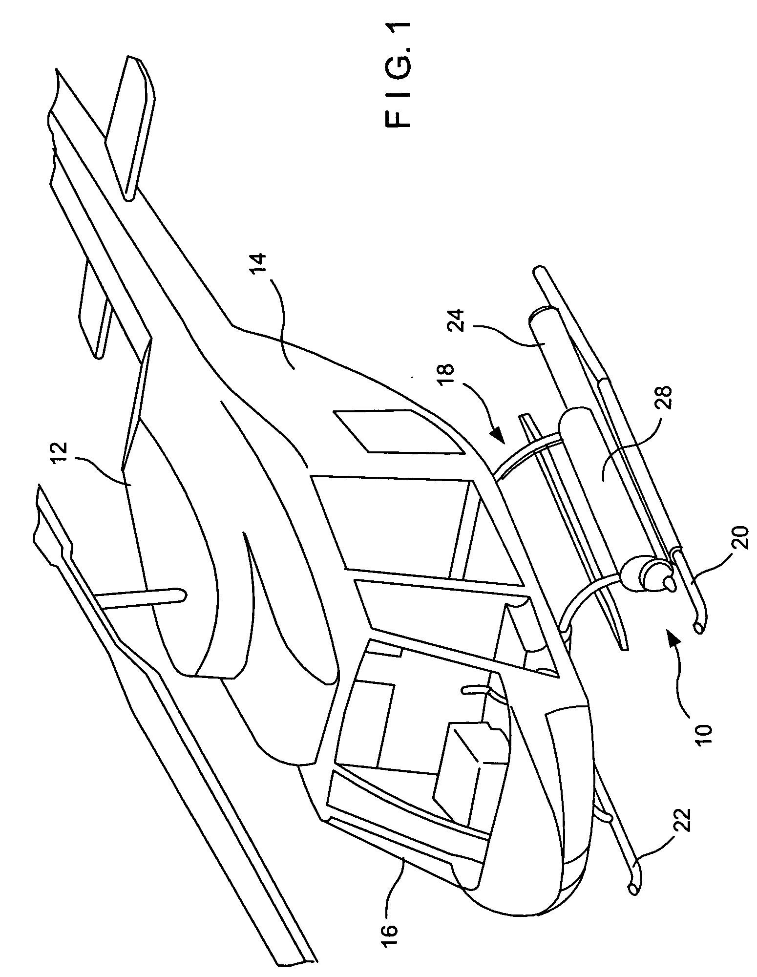
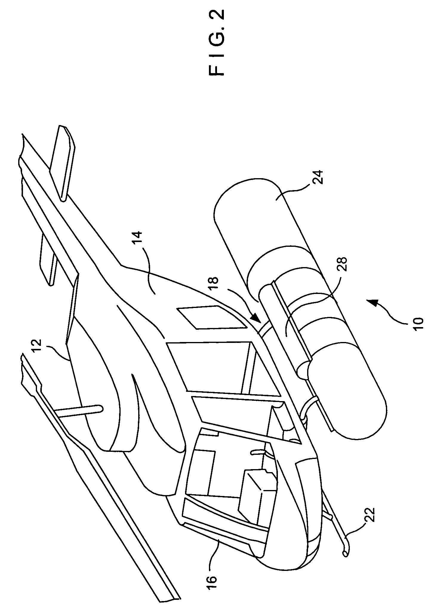
[0026]Referring now to the drawings in general and to FIGS. 1-3, specifically, wherein a helicopter or rotorcraft-type aircraft 12 employing the emergency floatation system 10 in accordance with exemplary embodiments of the invention is illustrated. The rotorcraft 12 includes a main body 14 with a cockpit 16, and a landing structure 18, having a first landing skid 20 and a second landing skid 22 extending along a longitudinal axis of the rotorcraft and adapted to engage the ground when not in flight.

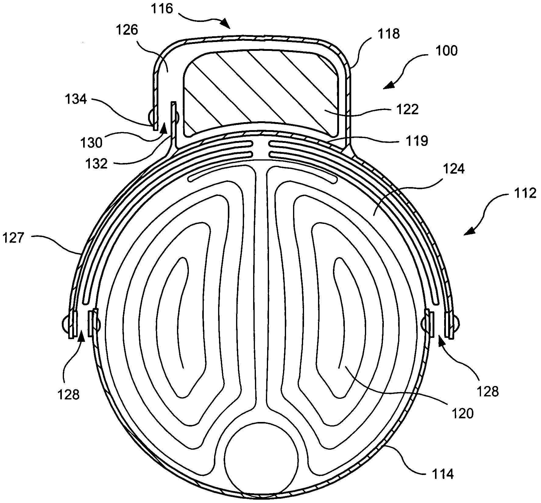
[0027]A pair of emergency floatation devices or inflatable floats 24 are connected to the first and second landing skids 20 and 22, respectively. It will be understood that more or less floatation devices can be provided on each leg of the landing structure 18. At least one inflatable life-raft module 28 is associated with each float. It will be discussed hereinbelow in substantial detail that the integrated emergency float-raft system 10 of the invention provides a simplified mounting a...


PUM


Abstract

An emergency floatation system associated with a landing gear of a rotorcraft comprising at least a float unit and a raft module. The float unit is formed by a base and a float cover with an inflatable float being positioned therebetween. The raft module is formed with a raft compartment adapted to receive an inflatable raft in the packed condition thereof. The raft module is supported on the float by the base. The raft is adapted for inflation and deployment from the raft module independently of the float deployment.

Description

FIELD OF THE INVENTION[0001]This invention relates in general to emergency floatation devices, and in particular, it relates to external rotorcraft floatation devices.BACKGROUND OF THE INVENTION[0002]Certain types of aircraft such a commercial fixed wing aircraft and rotorcraft such as, for example, helicopter-type aircraft, are required by federal regulatory agencies to carry inflatable floatation devices for passenger safety in the event of an emergency while flying over water. In the rotorcrafts, floatation devices and systems have also been employed in order to enable the craft to land on water in emergency situations, when, for example, the rotorcraft loses power. Such systems provide passengers with extra critical time before the rotorcraft sinks. Such emergency floatation systems typically include multiple emergency floatation devices mounted to the rotorcraft landing gear.[0003]Various prior art floatation devices have been used to support vehicles such as a helicopter on a ...

Claims


Application Information

Patent Timeline
Patent Type & Authority Patents(United States)
IPC IPC(8): B63B35/58
CPCB64C25/56B64C25/52B64C2025/325
Inventor HENRY, BRIAN T.SWIERKOCKI, THOMAS W.VEZZOSI, JONATHANGIBSON, BRIAN
Owner AIR CRUISERS
Why Eureka
Try Eureka