States encoding in multi-bit flash cells

a multi-bit flash cell and state encoding technology, applied in the field of flash memories, can solve the problems of reducing the number of orderings that can actually be used, 0” cannot be used, and ordering the bit patterns that require the threshold voltage to decreas

Active Publication Date: 2007-12-18
WESTERN DIGITAL ISRAEL LTD
View PDF9 Cites 136 Cited by
  • Summary
  • Abstract
  • Description
  • Claims
  • Application Information

AI Technical Summary

Problems solved by technology

However, there are restrictions put on the ordering because of the way the flash cells are programmed, and these restrictions reduce the number of orderings that can actually be used.
Second, assuming a design in which each bit resides in a different page, there are restrictions caused by the bits of a cell being written sequentially rather than all at once.
Therefore, any ordering of the bit patterns that requires the threshold voltage to decrease when writing a bit to “0” cannot be used.
This requires changing the threshold downward, from the state representing “10” to the state representing “00”, but as we noted above, this is impossible to do in typical flash devices.
se. However, as will be explained below, the method proposed by Takeuchi results in an ordering that is not opti

Method used


Image

  • States encoding in multi-bit flash cells
  • States encoding in multi-bit flash cells
  • States encoding in multi-bit flash cells

Examples


Embodiment Construction

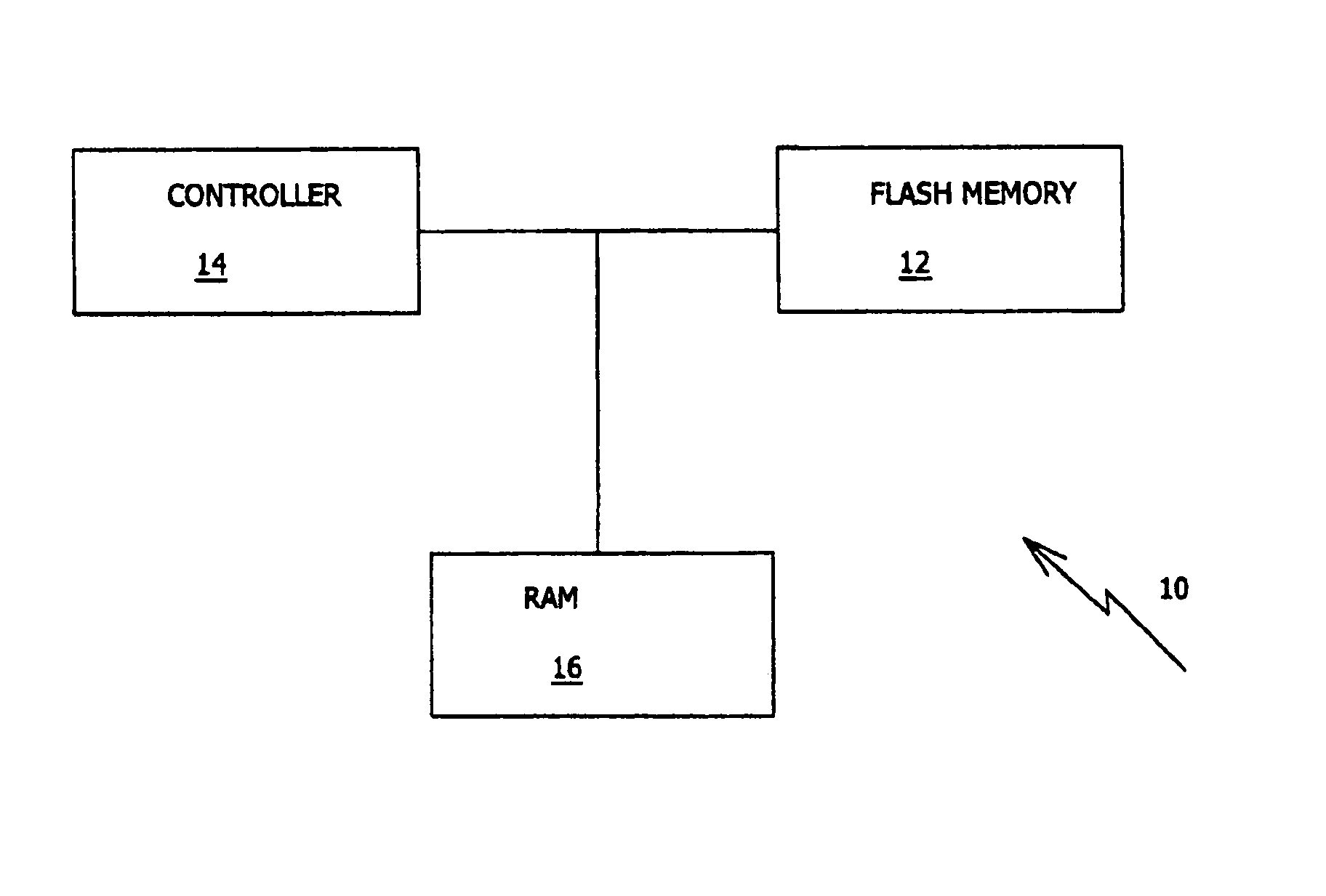
[0075]The present invention is of a method of programming multi-bit flash cells.

[0076]The principles and operation of a multi-bit-cell flash memory device according to the present invention may be better understood with reference to the drawings and the accompanying description.

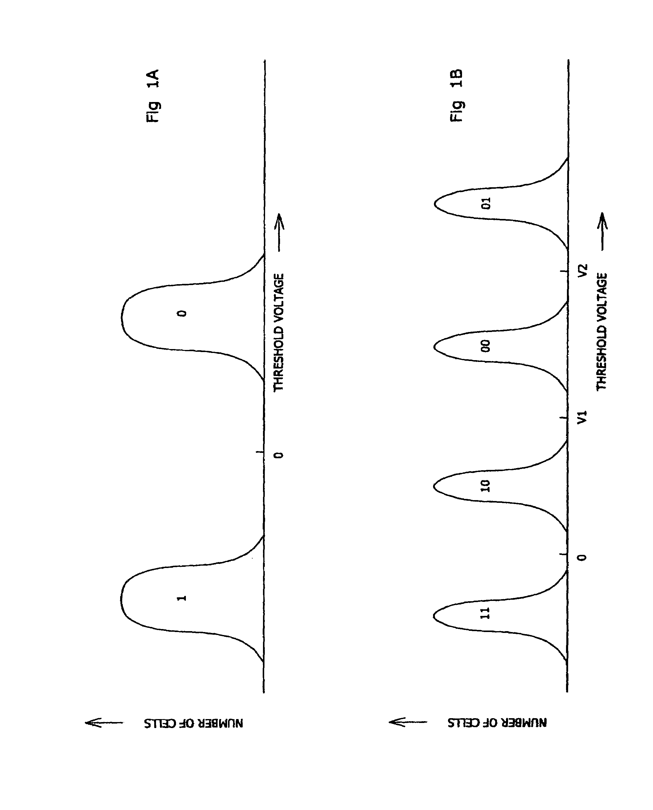
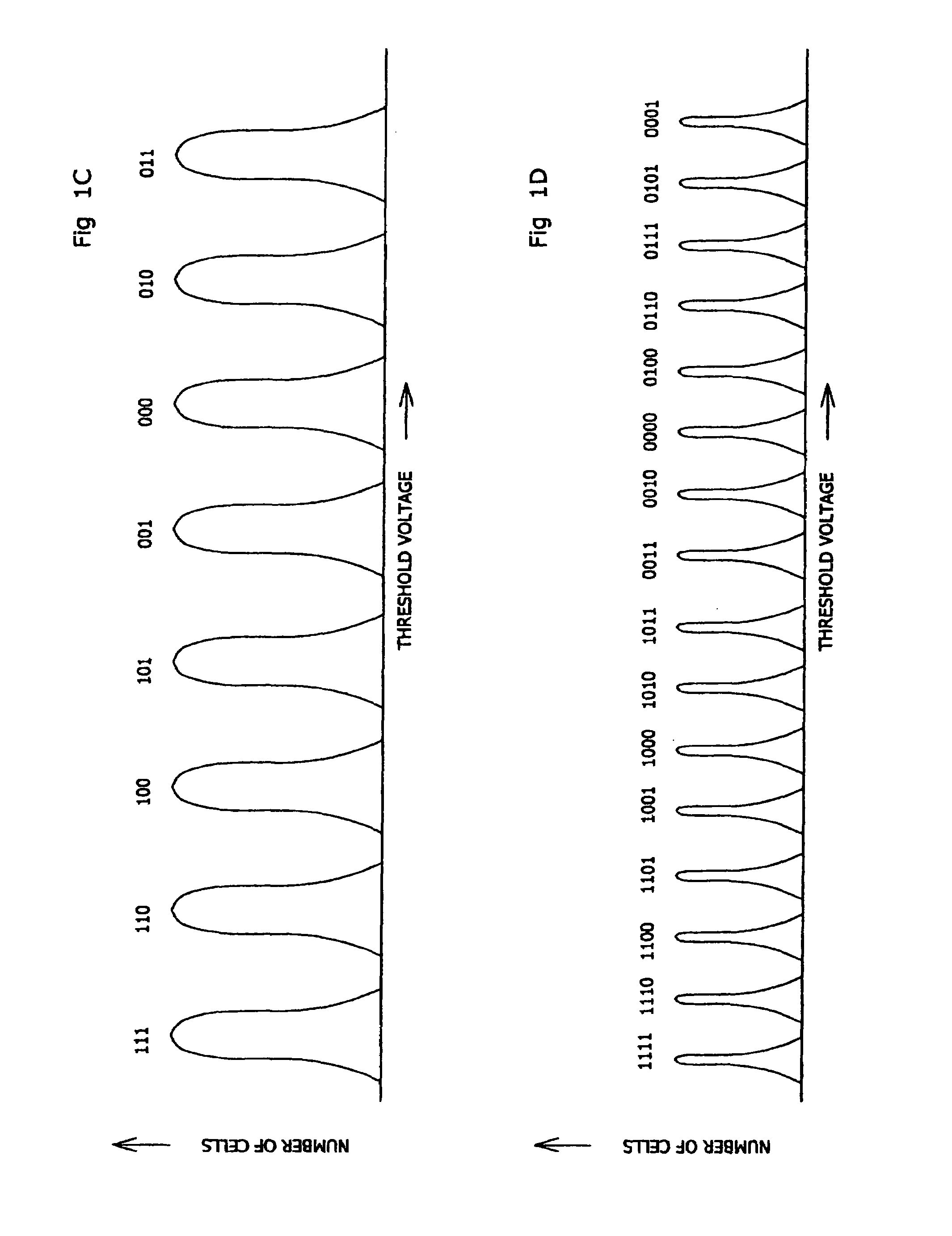
[0077]We now consider the question of what is a good ordering of the bit patterns in an n-bit MBC cell. There is no one clear-cut criterion to use for deciding what is “best”. Instead we present several different criteria to choose from. The best criterion to use in an actual design depends upon the requirements of the overall storage system, as is made clear in the discussion below.

[0078]We base our evaluation of orderings on the number of comparison operations required for reading the bits contained in an MBC cell. As already explained above, an SBC cell requires just one comparison of its threshold voltage value against a reference in order to determine the cell's data contents. A 2-bit MBC cell may requir...


PUM


Abstract

N data bits are stored in ┌N / M┐ cells by programming each cell with up to M of the bits according to a valid, nonserial bit ordering that satisfies one of the following criteria: Either the number of threshold voltage comparisons needed to read all M bits sequentially is at most 1 more than the smallest such number, or the largest number of threshold voltage comparisons needed to read any bit is minimized, or the smallest number of threshold voltage comparisons needed to read any bit is minimized, or the difference between the largest and smallest number of threshold voltage comparisons needed to read any bit statically is at most 1 more than the smallest such difference, or the difference between the largest and smallest number of threshold voltage comparisons needed to read any bit dynamically is minimized.

Description

[0001]This patent application claims the benefit of U.S. Provisional Patent Application No. 60 / 553,798, filed Mar. 14, 2004FIELD AND BACKGROUND OF THE INVENTION[0002]The present invention relates to flash memories and, more particularly, to a method of storing data in multi-bit flash cells.[0003]Flash memory devices have been known for many years. Typically, each cell within a flash memory stores one bit of information. Traditionally, the way to store a bit has been by supporting two states of the cell—one state represents a logical “0” and the other state represents a logical “1”. In a flash memory cell the two states are implemented by having a floating gate above the cell's channel (the area connecting the source and drain elements of the cell's transistor), and having two valid states for the amount of charge stored within this floating gate. Typically, one state is with zero charge in the floating gate and is the initial unwritten state of the cell after being erased (commonly ...

Claims


Application Information

Patent Timeline
Patent Type & Authority Patents(United States)
IPC IPC(8): H04L12/28H04L12/56
CPCG11C16/10G11C11/5628G11C7/1006G11C16/04
Inventor LASSER, MENAHEM
Owner WESTERN DIGITAL ISRAEL LTD
Why Eureka
Try Eureka