Image forming apparatus with controlled timing of contact of cleaning blade against intermediate transfer member

a technology of image forming apparatus and transfer member, which is applied in the direction of electrographic process apparatus, instruments, optics, etc., can solve the problems of deviation or distortion, deviation or distortion of obtained images, instability of transfer operation, etc., and achieve the effect of preventing the decrease of the number of achievable image formation per unit tim

Inactive Publication Date: 2007-12-18
SEIKO EPSON CORP
View PDF9 Cites 2 Cited by
  • Summary
  • Abstract
  • Description
  • Claims
  • Application Information

AI Technical Summary

Benefits of technology

[0018]It is therefore an object of the present invention to provide an image forming apparatus in which deviation or distortion hardly occurs in an image under primary transfer even when a recording medium is a thick sheet, while preventing the number of achievable image formation per unit time from being decreased when the recording medium is an ordinary sheet.
[0027]With this configuration, since the conveyance speed of the recording medium caused by the gate roller pair is set to be faster than the conveyance speed of the recording medium at the secondary transfer position, no tension acts on the recording medium between the gate roller pair and the secondary transfer position. Thus, when the recording medium has a stiffness no greater than the prescribed level, the transfer operation at the secondary transfer position becomes stable so that deviation or distortion does not occur in the image under the secondary transfer. Further, the circulating speed of the intermediate transfer member also becomes stable so that deviation or distortion is avoided similarly in the image at the primary transfer position.
[0028]Further, when the recording medium has a stiffness greater than the prescribed level, the cleaning blade is brought into contact with the intermediate transfer member after the trailing edge of the recording medium has passed the nipping position. Thus, at the time that the cleaning blade is brought into contact with the intermediate transfer member, a state is already established that a speed increasing force resulting from a compressive force does not act on the intermediate transfer member. Accordingly, at the time that the cleaning blade is brought into contact with the intermediate transfer member, the traveling speed of the intermediate transfer member is in a stable state.
[0033]This permits reliable fusing of the toner image onto the recording medium without the necessity of an increase in the heat generation rate of the fuser. Further, using the time duration that the recording medium and the intermediate transfer member are at low speeds, the cleaning blade can be brought into contact with the intermediate transfer member 51 after the primary transfer is completed. On the other hand, in a case where the recording medium has a stiffness no greater than the prescribed level, the number of achievable image formations per unit time can be maintained at a high rate.

Problems solved by technology

In such an image forming apparatus, if the cleaning blade would be brought into contact with the intermediate transfer member during the above-mentioned primary transfer, a vibration in the apparatus arising at the time of contact of the cleaning blade or a change in the moving load of the intermediate transfer member could easily cause deviation or distortion in the obtained image.
Then, this tension could serve as a load at the secondary transfer position, and thereby could cause instability in the transfer operation at the secondary transfer position (deviation or distortion could arise in the transferred image).
This compressive force acts such as to increase the traveling speed of the intermediate transfer member at the secondary transfer position, and hence tends to cause instability in the traveling speed of the intermediate transfer member.
Thus, in such a situation, when the cleaning blade is brought into contact with the intermediate transfer member, the traveling speed of the intermediate transfer member becomes more unstable so that the speed fluctuation increases.
This easily causes deviation or distortion in the image under the primary transfer in the above-mentioned primary transfer position.
Irrespective of the thickness of the recording medium, similar problem would arise in the case of a recording medium having a large stiffness that is enough to cause an increase in the traveling speed of the intermediate transfer member at the secondary transfer position and thereby causes an instability in the traveling speed of the intermediate transfer member.
Thus, in the present application, a “thick sheet” indicates a “recording medium having a large sheet stiffness that is enough to cause an increase in the traveling speed of the intermediate transfer member at the secondary transfer position and thereby causes an instability in the traveling speed of the intermediate transfer member.”

Method used


Image

  • Image forming apparatus with controlled timing of contact of cleaning blade against intermediate transfer member
  • Image forming apparatus with controlled timing of contact of cleaning blade against intermediate transfer member
  • Image forming apparatus with controlled timing of contact of cleaning blade against intermediate transfer member

Examples


Embodiment Construction

[0049]Embodiments of the invention will be described below in detail with reference to the accompanying drawings.

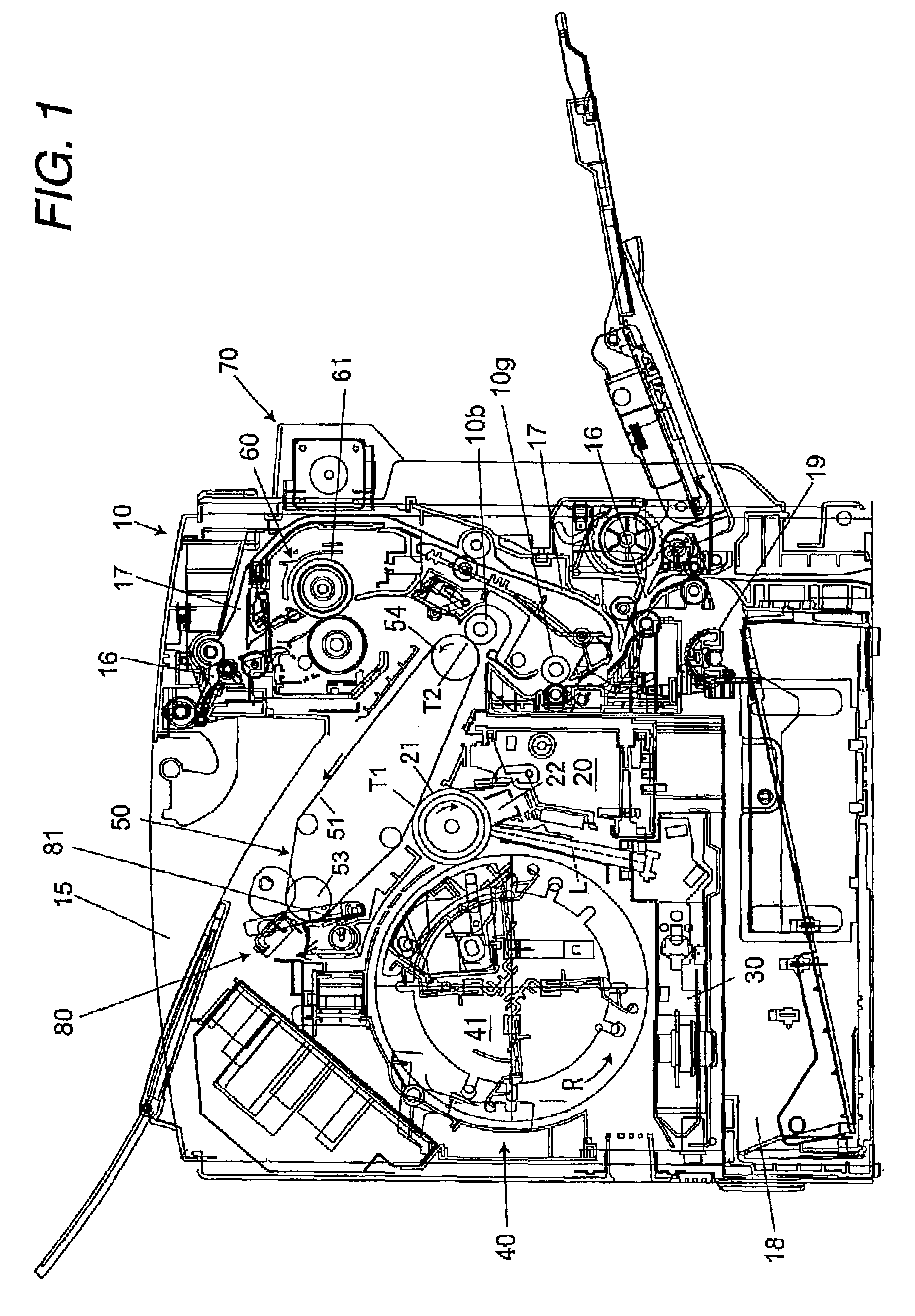
[0050]FIG. 1 shows an image forming apparatus according to one embodiment of the invention.

[0051]This image forming apparatus is adapted to longitudinally feed a sheet of A4 size (including the letter size) as a recording medium and then to form a full color image on both sides of the recording medium. The image forming apparatus comprises: a case 10; an image carrier unit 20 accommodated in the case 10; an exposure unit 30; a development unit 40; an intermediate transfer unit 50; and a fuser unit 60.

[0052]In the case 10, a frame of the main body of the apparatus is provided but not shown. Then, various units and the like are attached to this frame.

[0053]The image carrier unit 20 comprises: a photosensitive body 21 having a photosensitive layer in its outer periphery surface and thereby serving as an image carrier; and a corona electrostatic charger (scorotron electrostat...


PUM


Abstract

A circulating intermediate transfer member contacts an image carrier at a primary transfer position at which a toner image is transferred onto the intermediate transfer member. A secondary transfer member contacts the intermediate transfer member at a secondary transfer position at which the toner image is transferred onto a recording medium. A gate roller pair nips the recording medium therebetween at a nipping position and conveys the recording medium toward the secondary transfer position. A cleaning blade retractably contacts and scrapes off toner remaining on the intermediate transfer member. A conveyance speed of the recording medium at the nipping position is faster than that at the secondary transfer position. The cleaning blade is retracted from the intermediate transfer member until a trailing end of the recording medium passes through the nipping position, when the recording medium has a stiffness greater than a prescribed level.

Description

BACKGROUND OF THE INVENTION[0001]The present invention relates to an image forming apparatus such as a printer, a facsimile machine, and a copying machine that forms a toner image using electrophotography.[0002]Japanese Patent Publication No. 2003-195712A discloses an image forming apparatus that comprises:[0003]an image carrier on which a toner image is formed;[0004]an intermediate transfer member for forming a primary transfer position contacting the image carrier so as to perform primary transfer of the toner image on the image carrier, and then forming a secondary transfer position contacting a recording medium so as to transfer the toner image onto the recording medium;[0005]a secondary transfer roller brought into press contact with the intermediate transfer member via the recording medium at the secondary transfer position;[0006]a gate roller pair arranged in an immediate vicinity of a preceding stage of the secondary transfer position relative to a direction of conveyance of...

Claims


Application Information

Patent Timeline
Patent Type & Authority Patents(United States)
IPC IPC(8): G03G15/00G03G15/14G03G21/00
CPCG03G15/0131G03G15/161G03G2215/0177G03G2215/0154
Inventor MIZUSHIMA, NOBUYUKITANAKA, KUNIAKITAGUCHI, KEIICHI
Owner SEIKO EPSON CORP
Why Eureka
Try Eureka