
Model management technology using grouping of features

a technology of model management and features, applied in the field of model management technology using grouping of features, can solve the problems of not always intuitive, re-designing the part is too time-consuming, modeling a part may require a great deal of planning and expertise, etc., and achieve the effect of facilitating explicit specification of scope definition

Inactive Publication Date: 2007-12-25
DASSAULT SYST SOLIDWORKS CORP
View PDF5 Cites 30 Cited by
  • Summary
  • Abstract
  • Description
  • Claims
  • Application Information

AI Technical Summary

Benefits of technology

[0019]Further aspects include optimizing the feature chains and inputting the combination of the feature chains, which prescribes the regeneration order, into a process that generates a part. Moreover, the scope definition can be based on feature object existence, on feature object proximity, or on a combination of feature object existence and feature object proximity. Implementations can enable the user to issue an instruction to modify the scope definition, whereby the instruction explicitly specifies either a feature object to include in the scope definition or a feature object to exclude from the scope definition. Additionally, a user interface dialog can facilitate the explicit specification of the scope definition.

Problems solved by technology

While building a part, the order in which a design engineer should introduce features and direct the system to perform operations is not always intuitive.
Some design engineers may decide that re-designing the part is too time-consuming.
Due to the problem of introducing features in a particular order, modeling a part may require a great deal of planning and expertise.
The ordering problem is present throughout the modeling process.
The difficulty of the ordering problem may increase as the modeling process progresses because as a part becomes more complex, the design engineer has more difficulty determining the correct feature order.
Often the design engineer discovers that the feature order results in the creation of a physically incorrect part.
Therefore, a burden is placed on the design engineer to recreate portions of the part or the entire part, re-order the features that constitute the part, or in some other tedious manner, correct the inaccurate geometry.
The design engineer spends an enormous amount of time and effort during the 3D modeling process controlling the feature order and the feature order's effect on the final geometric representation of a part.

Method used


Image

  • Model management technology using grouping of features
  • Model management technology using grouping of features
  • Model management technology using grouping of features

Examples


Embodiment Construction

[0036]The present invention allows design engineers to design components without worrying about feature order. This is achieved by separating the concepts of feature creation order and feature regeneration order. Therefore, the order in which a user adds features to a component is independent of the order in which the geometric feature operations (e.g., applying a boss or applying a cut) are applied to the underlying geometric model. The present invention provides a mechanism that automatically determines feature regeneration order independent of the user's feature creation order. Such an automated mechanism saves the design engineer an enormous amount of time and effort during the 3D modeling process because he or she is freed from redesigning parts and / or manipulating the order of features to correct geometry. Unlike conventional feature-based modeling systems wherein the feature regeneration order is defined and controlled solely by the user, the present invention controls the re...


PUM


Abstract

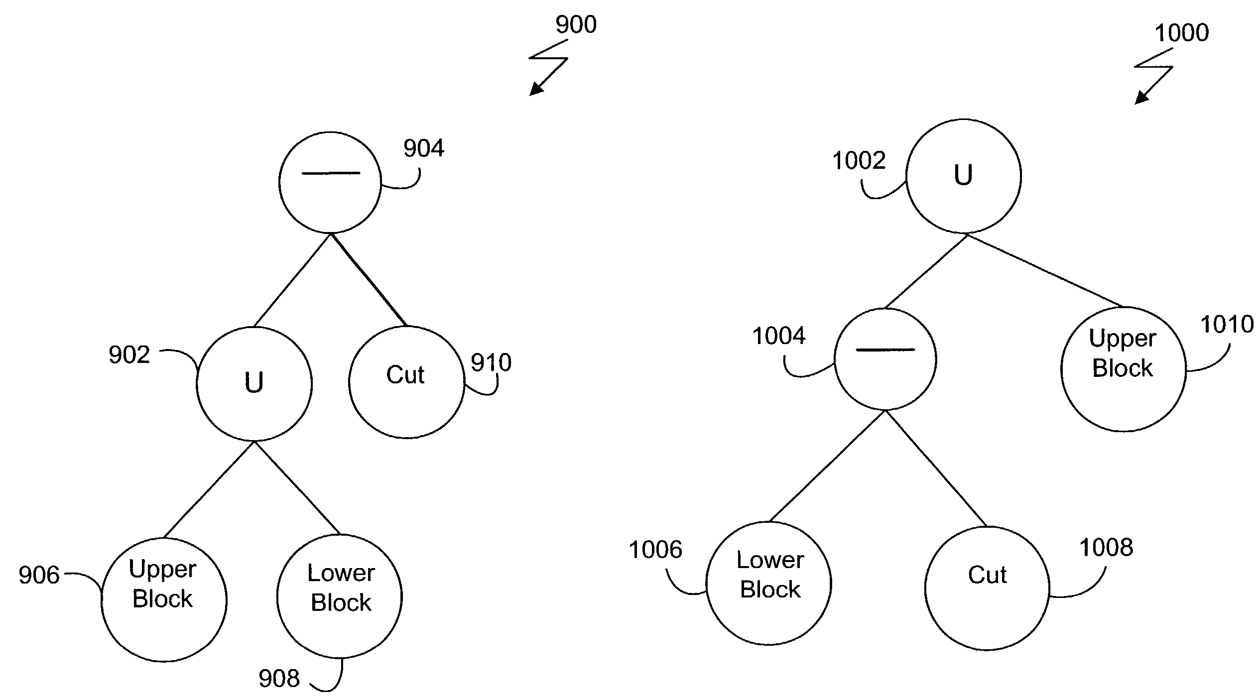
Modeling of a three-dimensional object includes storing data representing a computer model of the three-dimensional object. The data includes a number of feature objects each of which defines a feature of the computer model. A feature chain is formed and includes at least one feature object having a design effect limited in scope such that an operation for removing material operates to affect the feature of the computer model defined by another feature object in the same feature chain and does not affect the feature of the computer model defined by the feature object not in said same feature chain. Multiple feature chains can be combined to form an interrelationship among feature objects that represents a hierarchy defining construction of the model from the feature objects.

Description

[0001]This application claims priority from U.S. provisional patent application No. 60 / 329,490, filed Oct. 15, 2001, and titled “Model Management Technology Using Feature Chains.”BACKGROUND OF THE INVENTION[0002]Computer-aided design (CAD) software allows a user to construct and manipulate complex three-dimensional (3D) models of assembly designs. A number of different modeling techniques can be used to create a model of an assembly. These techniques include solid modeling, wire-frame modeling, and surface modeling. Solid modeling techniques provide for topological 3D models, where the 3D model is a collection of interconnected edges and faces, for example. Geometrically, a 3D solid model is a collection of trimmed surfaces. The trimmed surfaces correspond to the topological faces bounded by the edges. Wire-frame modeling techniques, on the other hand, can be used to represent a model as a collection of simple 3D lines, whereas surface modeling can be used to represent a model as a ...

Claims


Application Information

Patent Timeline
Patent Type & Authority Patents(United States)
IPC IPC(8): G06F17/50G06T15/00G06T17/10G06T17/40
CPCG06T17/10
Inventor CHIN, RICARDOZUFFANTE, ROBERT P.BARAN, ILYA
Owner DASSAULT SYST SOLIDWORKS CORP
Learn More