
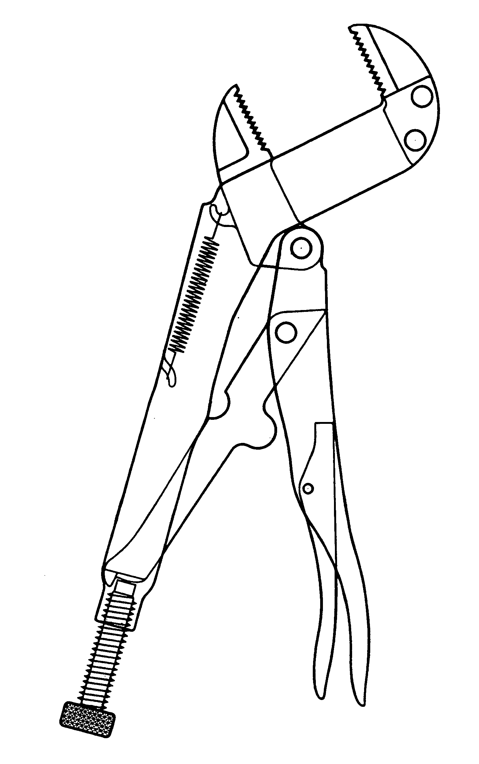
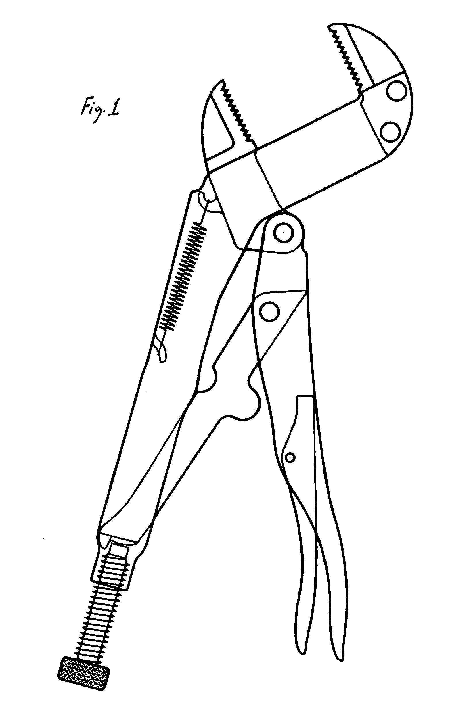
Parallel jaw locking toggle pliers/wrench

a toggle plier and parallel jaw technology, which is applied in the direction of pliers, clamps, wrenches, etc., can solve the problems of jaw slippage, subsequent readjustment, and difficulty in releasing the movable lower jaw member from the side edge length dimensions of the support member, so as to increase the mechanical advantage, the handle and toggle position can be easily determined, and the work efficiency is increased.

Inactive Publication Date: 2008-01-01
TORTOLANI JR KENNETH GUY
View PDF39 Cites 37 Cited by
  • Summary
  • Abstract
  • Description
  • Claims
  • Application Information

AI Technical Summary

Benefits of technology

[0025]In consideration of the foregoing, an advantage of the Invention is a reduction in jaw slippage accomplished with parallel jaw members having a symmetrical clamping force applied to surface area of the jaw members and the object (or objects) being clamped.
[0026]Another advantage of the Invention is an easily determined handle and toggle position combined with a securable toggle stop. This combination allows for the increase in work efficiency by not having to repeatedly readjust the handle and toggle position angle to determine the proper clamping pressure during the clamping / releasing procedure.
[0027]Still another advantage of the Invention is an increased mechanical advantage provided by locating a movable upper handle over a fixed lower handle—resulting in an increase in work efficiency during the clamping procedure.
[0028]Yet another advantage of the Invention is an ergonomic / economic design of handle construction that reduces manufacturing cost, which in turn reduces consumer cost, while at the same adds value to the consumer by offering an affordable hand tool with handles that are ergonomic in shape.
[0029]A further advantage of the Invention is a reduction in cost by having a support member with integral strengthening ribs serving the dual purpose of providing rigidity to the support member, and providing a track assembly with accurate guide sections, for the purpose of maintaining the parallelism of the jaw members.
[0030]A still further advantage of the Invention is an increase in work efficiency by providing a wide range of release lever mechanisms specifically designed for users with different hand tool preferences. Simply stated: The more comfortable and familiar the user is when using the Invention, the more productive the user will be when completing a task with the Invention.

Problems solved by technology

This binding pressure makes releasing the movable lower jaw member from the side edge length dimensions of the support member difficult to impossible during the upper handle and jaw release of clamping pressure from the clamped object.
The disadvantages of conventional toggle locking pliers and automatic adjusting locking pliers are that the jaw members are not always in parallel relationship—resulting in jaw slippage from less surface area contact with a substantially square object (or objects) being clamped.
Furthermore, conventional toggle locking pliers and automatic adjusting locking pliers have the jaw width adjustment (toggle angle adjustment) being difficult to determine and keep secure during the clamping procedure—resulting in an awkward over adjustment and subsequent readjustment of an adjustment screw or toggle stop screw before different size objects are to be clamped.
The disadvantages of the previously mentioned parallel grip toggle locking pliers are that the lower jaw members are not always in a ninety degree angle relationship with a rectangularly shaped support member—resulting in jaw slippage from less surface area contact with a substantially square object (or objects) being clamped.
This type of fixed upper handle construction results in a lost of mechanical leverage gained by gravity, because the user of parallel grip toggle locking pliers has to rely on finger grip strength alone when squeezing the movable lower handle towards the fixed upper handle, rather than using body weight to help assist in pushing down on and squeezing a movable upper handle towards a fixed lower handle.
A further disadvantage of parallel action toggle locking wrenches and parallel grip toggle locking pliers is that handle construction is not of ergonomic design.
This results in an uncomfortableness and awkwardness during handle operation by the reduction of hand grip.
A still further disadvantage of parallel action toggle locking wrenches is a fixed lower handle design having an externally mounted toggle adjustment assembly—resulting in an awkwardness during handle operation by the reduction of hand grip.
This is because there is a greater possibility of the user grabbing onto the uncomfortable surface of the threaded section of the tool.
Another disadvantage of conventional toggle locking pliers, parallel action toggle locking pliers, and automatic adjusting locking pliers is cost of manufacture.
Still other disadvantages of automatic adjusting locking pliers are the awkward release of the locking mechanism, and the awkward position of the locking mechanism when in the unlocked mode, and jaw members being not parallel when clamped.

Method used


Image

  • Parallel jaw locking toggle pliers/wrench
  • Parallel jaw locking toggle pliers/wrench
  • Parallel jaw locking toggle pliers/wrench

Examples


Embodiment Construction

[0337]It should be known: Combining two of the related two dimensional Figures depicted herein (for example, combining a side view with a top view of the same part) contains the necessary information for the deduction of a third dimensional view from the related two dimensional Figures depicted; and therefore, one having ordinary skill in the art would have no difficulty in fabricating the following mechanisms as described herein.

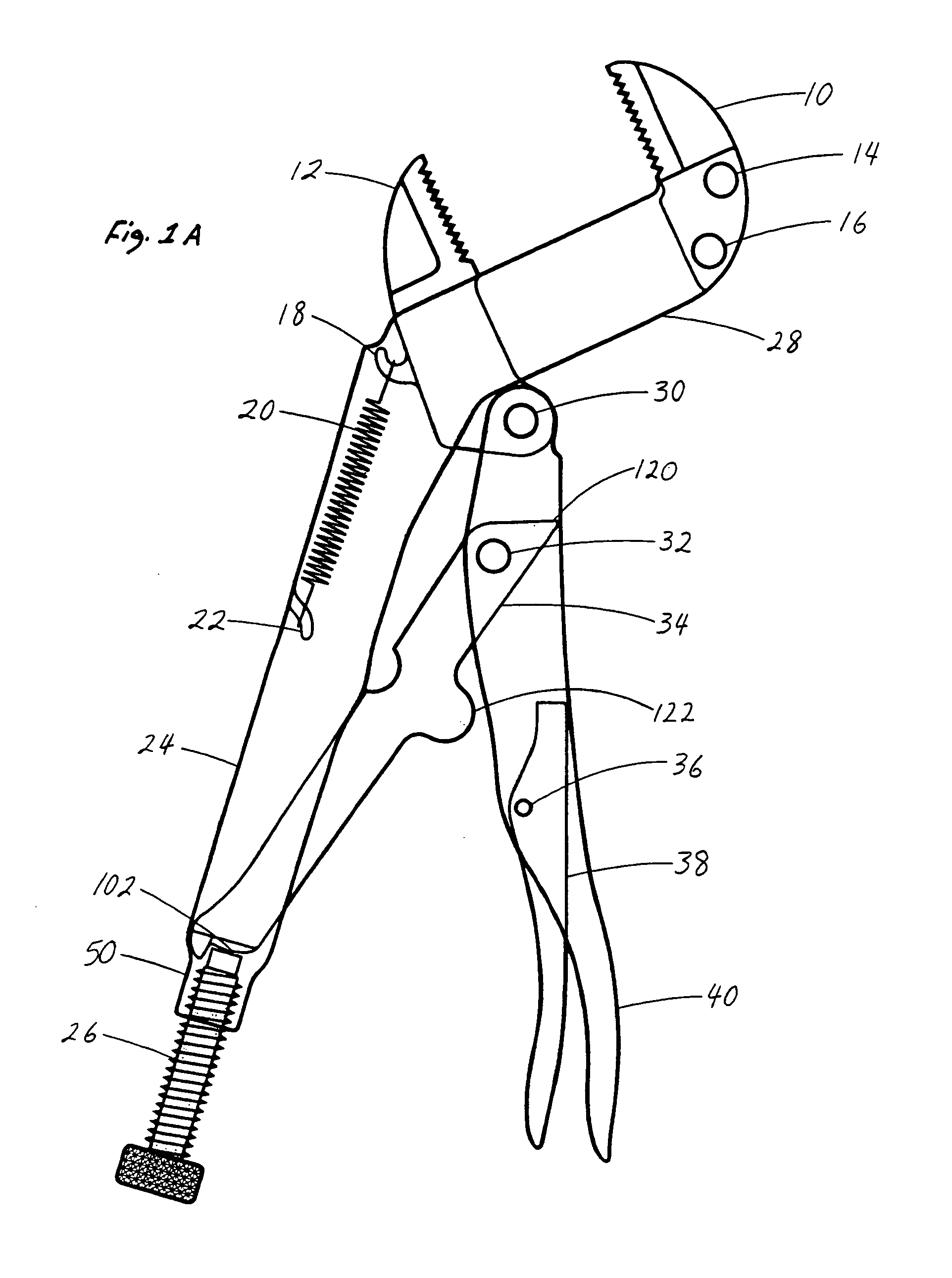
[0338]FIG. 1 and FIG. 1A depict the working relationship of mechanisms (some details not shown) being under spring tension—with jaw members in the fully open position.

[0339]FIG. 2 is a cross-section of lower handle 24: Other cross-section of lower handle 24 is not shown. Both cross-sections of lower handle 24 have the same dimensions. Rivet holes 42 and 44 depicted in the specification, are formed into lower handle 24 by a pressing / shearing process or by drilling (or by means known in the art). Hook 22 is formed by a pressing / shearing process (or by means k...


PUM


Abstract

A hand tool embodying a wrench or pliers having: a fixed upper jaw being in parallel relationship to a movable lower jaw; the upper jaw integrally constructed to a rectangular support member; the support member integrally formed to a horizontal fixed lower handle; the lower jaw slidable in and contiguous to the support member; the lower jaw made attachable to a rotatable upper handle; the upper handle being opposed over the lower handle; a spring mechanism tensioned to urge the lower jaw, the upper handle, a toggle mechanism and a release lever mechanism away from and backwards of the upper jaw; an adjustment screw or toggle screw mechanism rotatable for an adjustment angle of the toggle; the release lever made rotatable in the upper handle; the release lever levered off of the toggle; and a compound toggle link mechanism levered off of the toggle as an alternate release lever design.

Description

CROSS-REFERENCE TO RELATED APPLICATIONS[0001]This is a Continuation-In-Part Application of my earlier filed nonprovisional application: “PARALLEL JAW LOCKING TOGGLE WRENCH / PLIERS WITH ECONOMIC / ERGONOMIC HANDLES”—application Ser. No. 10 / 461,988—Filing Date Jun. 13, 2003 now U.S. Pat. No. 7,086,312; and discloses information contained in my earlier filed nonprovisional application: “PARALLEL JAW LOCKING TOGGLE PLIERS / WRENCH WITH ERGONOMIC / ECONOMIC HANDLES”—application Ser. No. 10 / 034,684—Filing Date Dec. 28, 2001, now abandoned; and discloses information contained in my earlier filed nonprovisional application: “PARALLEL JAW LOCKING PLIERS WITH MODIFIED ERGONOMIC / ECONOMIC HANDLES”—application Ser. No. 09 / 654,870—Filing Date Sep. 1, 2000, now abandoned; and discloses information contained in my earlier filed provisional applications: “PARALLEL JAW LOCKING PLIERS”—Appn. No. 60 / 138,571—Filing Date Jun. 11, 1999 and “PARALLEL JAW LOCKING PLIERS WITH ERGONOMIC HANDLES”—Appn. No. 60 / 267,914...

Claims


Application Information

Patent Timeline
Patent Type & Authority Patents(United States)
IPC IPC(8): B25B7/12B25B9/04B25B5/12
CPCB25B5/127B25B5/163B25B5/166B25B7/10B25B7/12B25B7/123B25B13/12B25B13/26
Inventor TORTOLANI, JR., KENNETH GUY
Owner TORTOLANI JR KENNETH GUY
Learn More