Adjustable handle for portable tool

a portable tool and adjustable technology, applied in the direction of portable power-driven tools, manufacturing tools, wing knobs, etc., can solve the problems of user's arm muscles ache, user's considerable muscular effort to maintain the tool position, etc., to facilitate different orientations of tool use and substantially different operations

Inactive Publication Date: 2008-01-01
TORO CO THE
View PDF53 Cites 42 Cited by
  • Summary
  • Abstract
  • Description
  • Claims
  • Application Information

AI Technical Summary

Problems solved by technology

When the work tool is at the end of a relatively long shaft, the user has to apply considerable muscular effort to maintain the tool in position.
The arm muscles of the user can therefore begin to ache after operating the tool over a period of time.

Method used


Image

  • Adjustable handle for portable tool
  • Adjustable handle for portable tool
  • Adjustable handle for portable tool

Examples


Embodiment Construction

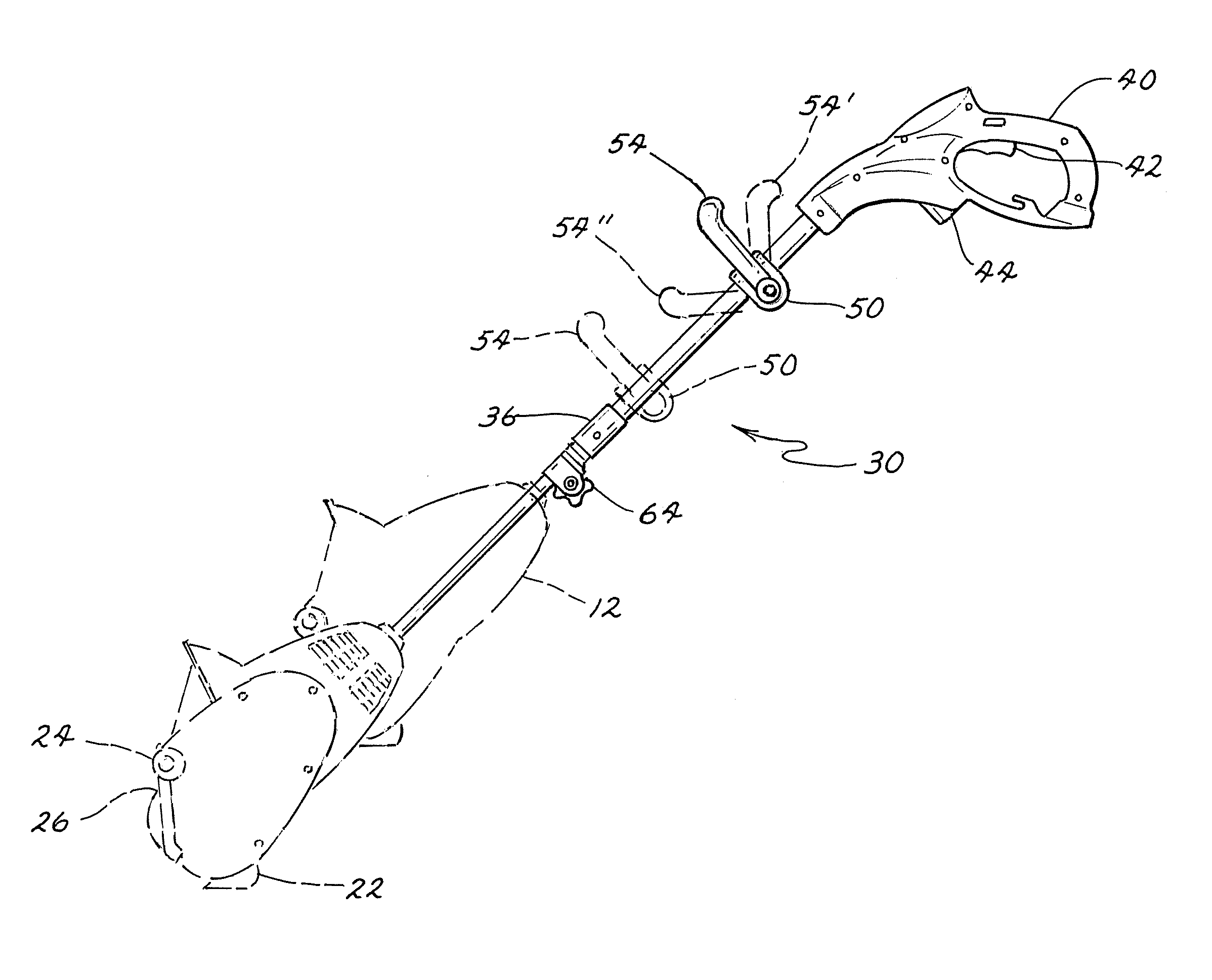
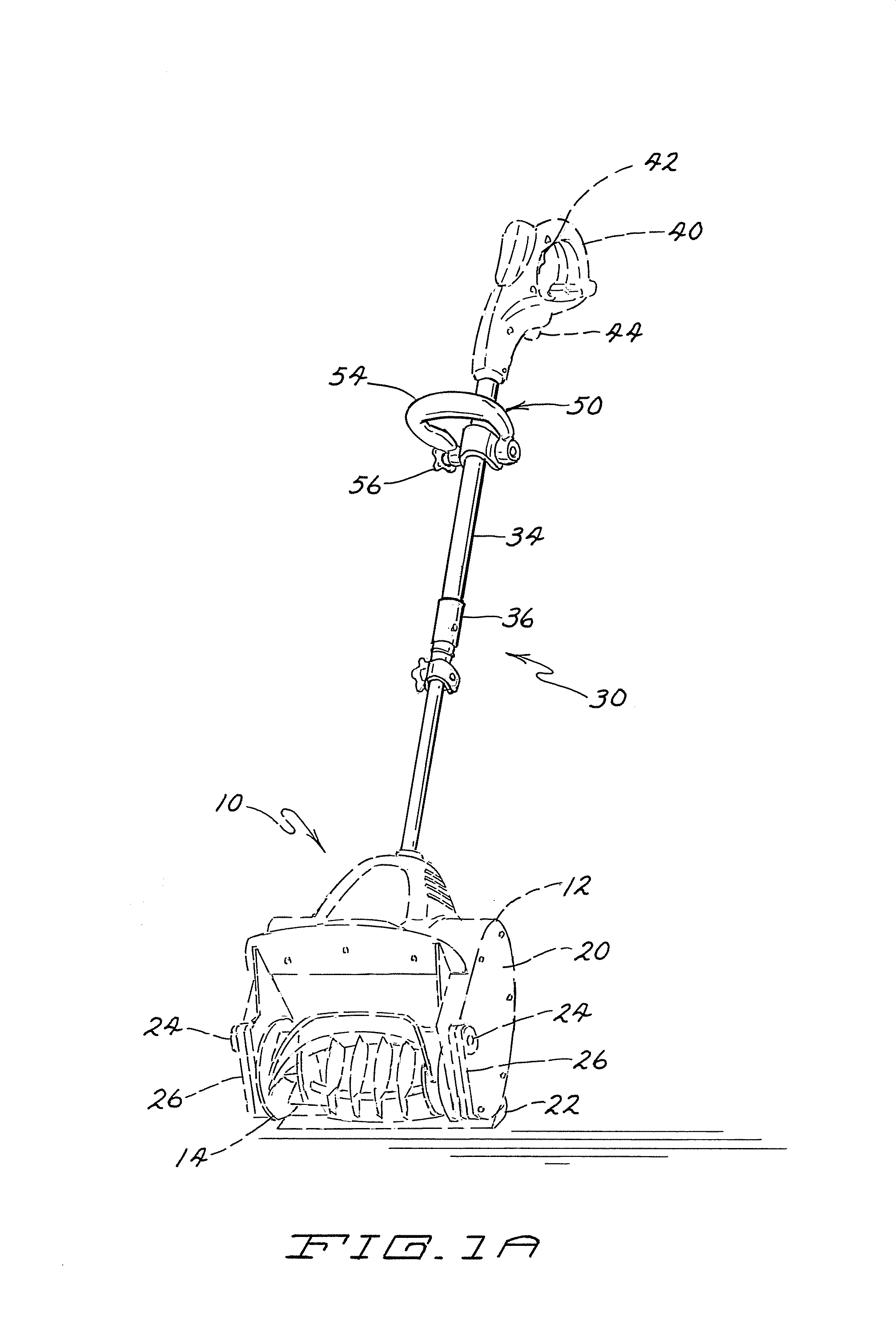
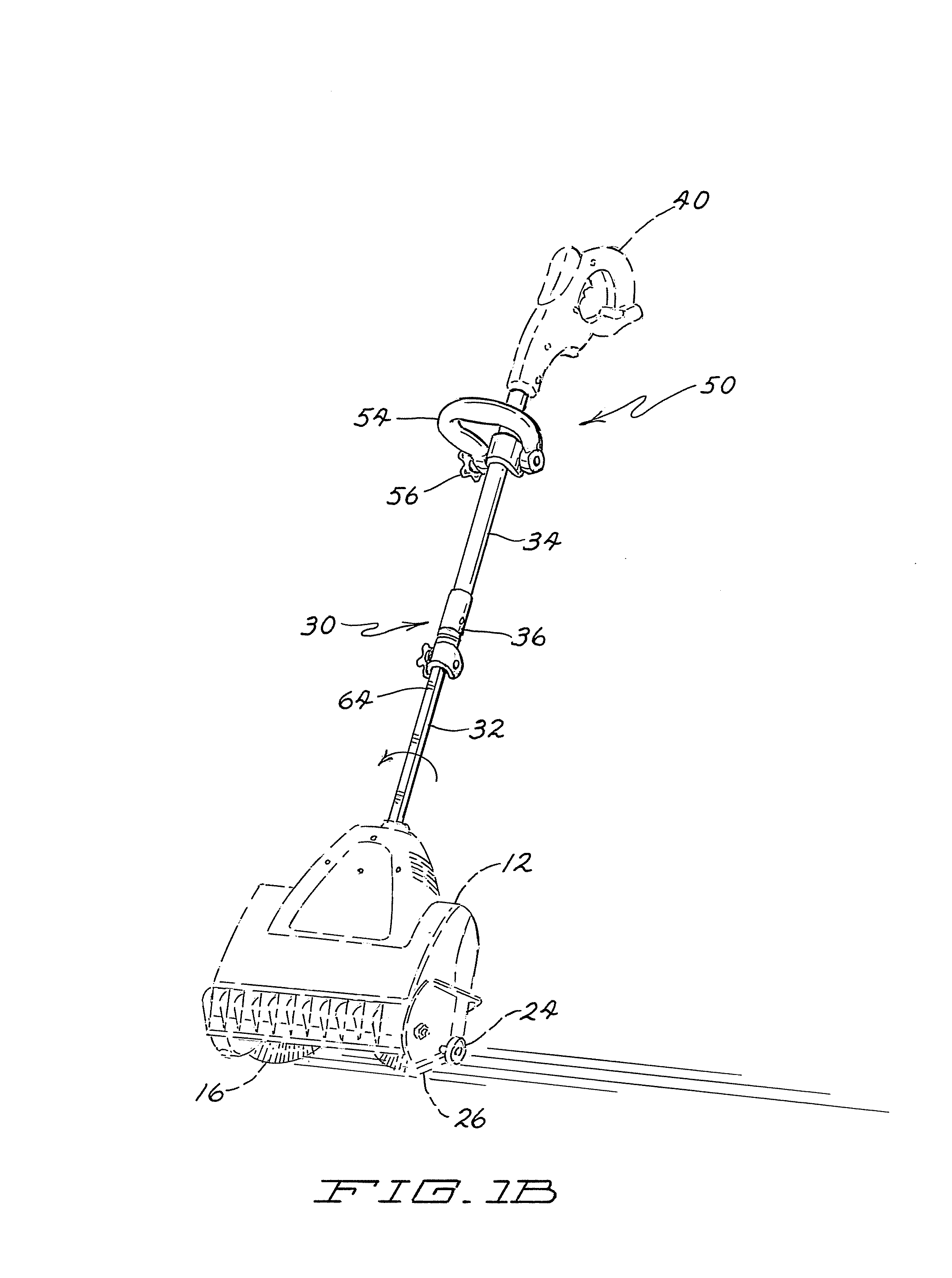
[0022]Referring to FIGS. 1a and 1b, a yard tool incorporating aspects of the present invention is generally illustrated as 10. Yard tool 10 includes a housing 12 within which a rotatable implement is positioned. Different rotatable implements may be contained within housing 12 including, for example, a snow-engaging impeller 14 of FIG. 1a and a generally cylindrical broom 16 of FIG. 1b. Implements 14, 16 are interchangeable and are selectively mounted for rotation inside housing 12 depending on the intended use of the yard tool 10. Two modes of operation of the yard tool 10 include a snow throwing mode and a debris sweeping mode. Other portable hand-held tools including, but not limited, to string trimmers, lawn edgers and powered brooms could utilize a handle assembly according to the present invention.

[0023]An electric drive motor 20 is positioned within housing 12 for powering the rotating implement 14, 16. Tool 10 can be supported upon surfaces by a scraper bar 22, by wheels 24,...


PUM


Abstract

A handle having an adjustable shaft wherein the overall length of the shaft and / or the angular relationship of portions of the shaft can be varied by a user of an associated tool. In one embodiment, the handle includes a first tube, a second tube connected to a working unit of a portable tool, and wherein a portion of the second tube is telescopically received into the first tube. A coupling is provided to receive a portion of the first tube and the second tube. The coupling has a pin stop which engages a pin connected to one of the tubes and defines a limit of a range of relative rotational motion between the first tube and the second tube. In one embodiment, the upper tubular portion of the handle and a control grip are capable of being rotated relative to a working unit.

Description

TECHNICAL FIELD[0001]This invention relates in general to a handle for a hand-held tool. More particularly, this invention relates to an adjustable handle for a hand-held portable tool.DESCRIPTION OF THE PRIOR ART[0002]Yard tools having a powered work tool at one end of a handle shaft are well known. For example, hand-held snow throwers have been developed and used in place of manual snow shoveling. These devices usually include a housing having some type of snow impelling mechanism, e.g. a rotatable rotor. These snowthrowers are configured to act much like a shovel and, in fact, is manipulated by the user in a manner similar to a shovel. The snowthrowers have a small housing at one end of an elongated handle that extends upwardly from the housing. The housing includes a relatively open reel-type impeller and a small electric motor for rotating the impeller. As the impeller rotates, the blades of the impeller contact and move the snow through the housing. One such electric snowthrow...

Claims


Application Information

Patent Timeline
Patent Type & Authority Patents(United States)
IPC IPC(8): A01B1/00
CPCE01H5/04Y10T16/44B25F5/026
Inventor SHAFFER, CHADWICK A.HURST, JOHN O.
Owner TORO CO THE
Why Eureka
Try Eureka