Vehicle chassis with side mounted air intake plenum

Active Publication Date: 2008-01-01
DAIMLER TRUCKS NORTH AMERICA
View PDF11 Cites 1 Cited by
  • Summary
  • Abstract
  • Description
  • Claims
  • Application Information

AI Technical Summary

Benefits of technology

[0004]Therefore, a need exists for improved air-intake

Problems solved by technology

However, such systems suffer from a number of drawbacks such as difficulties in installation, inefficiencies in air delivery, and problems associated with the maintenance of such systems.

Method used


Image

  • Vehicle chassis with side mounted air intake plenum
  • Vehicle chassis with side mounted air intake plenum
  • Vehicle chassis with side mounted air intake plenum

Examples


Embodiment Construction

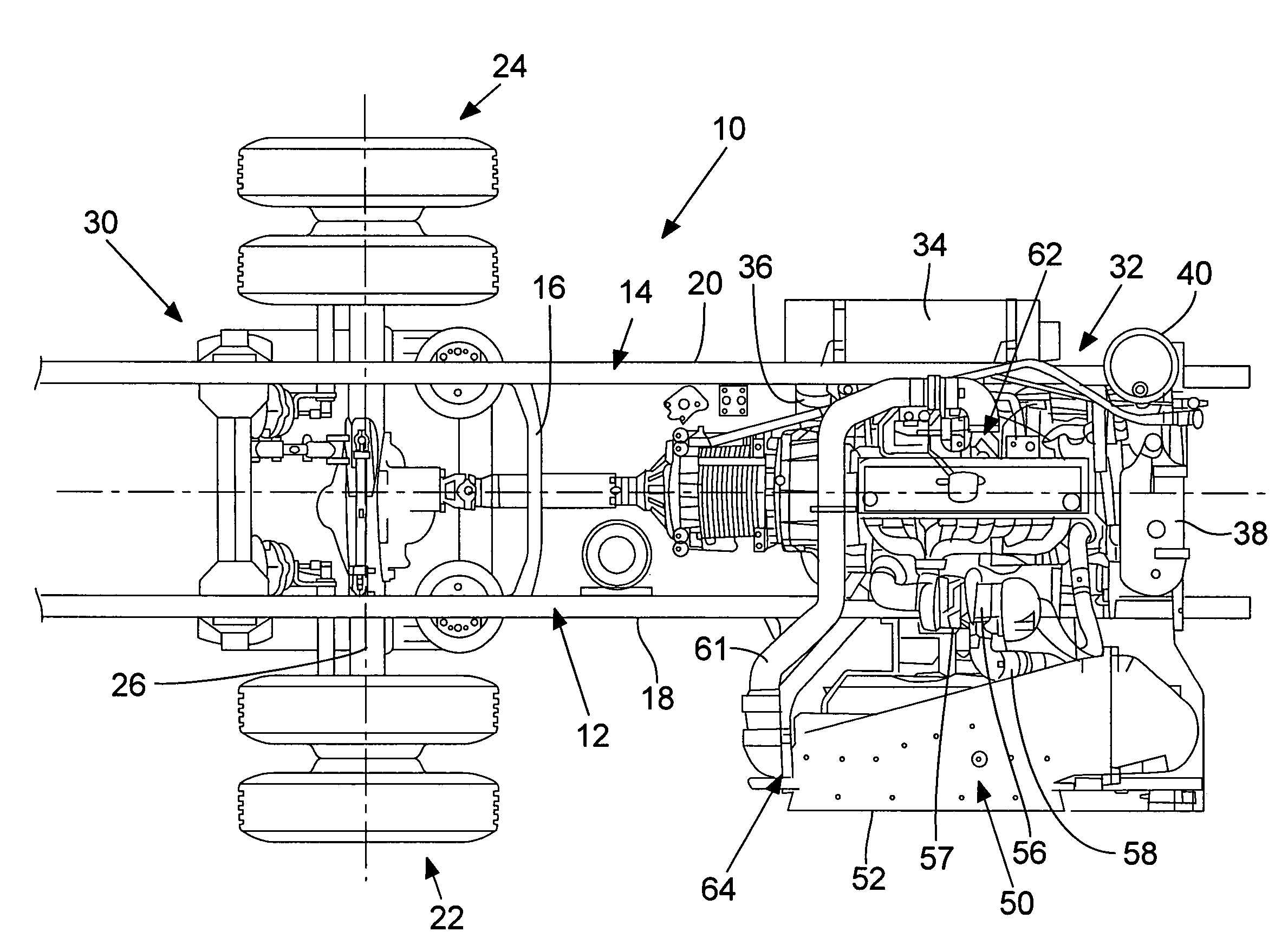
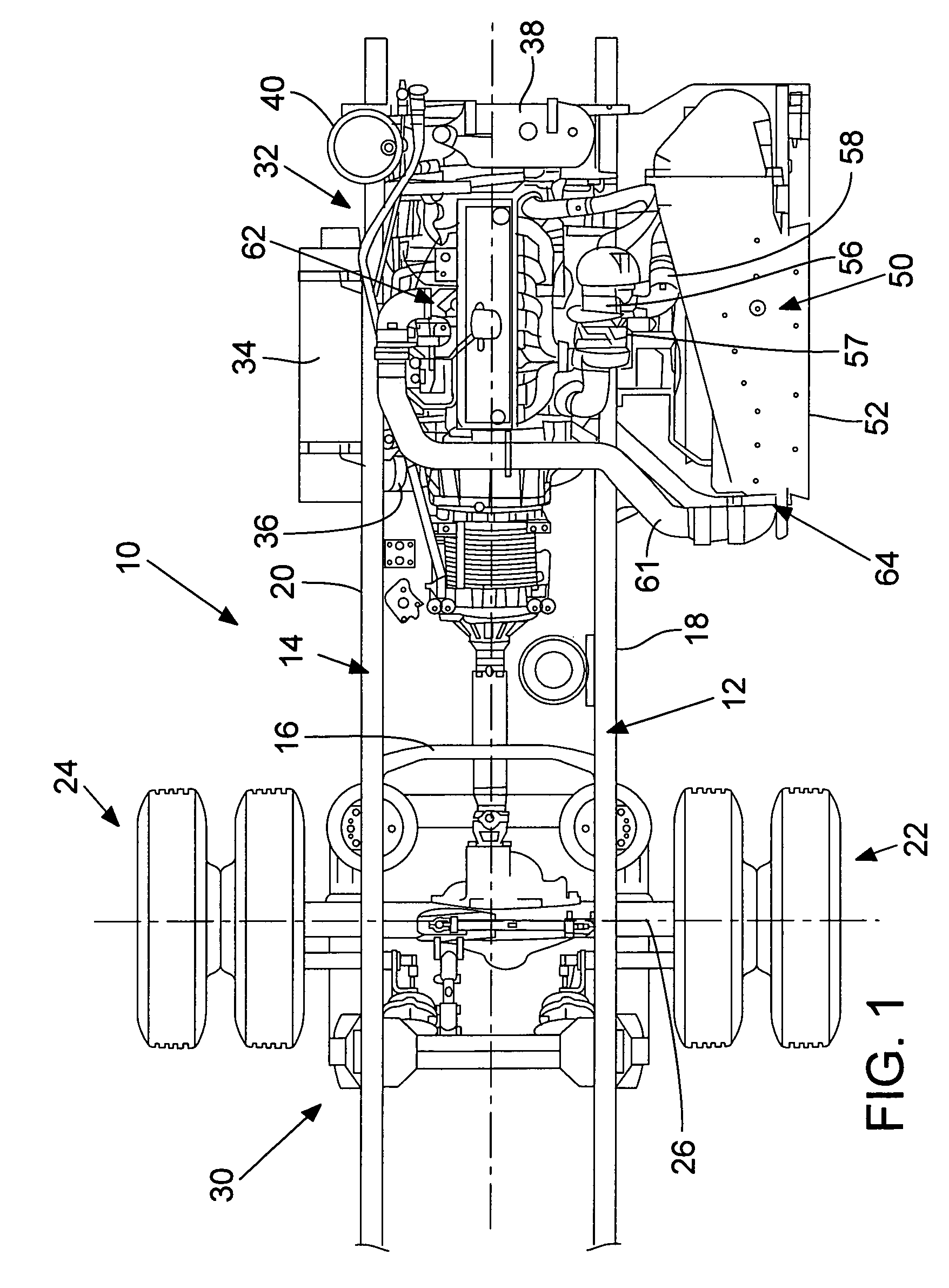
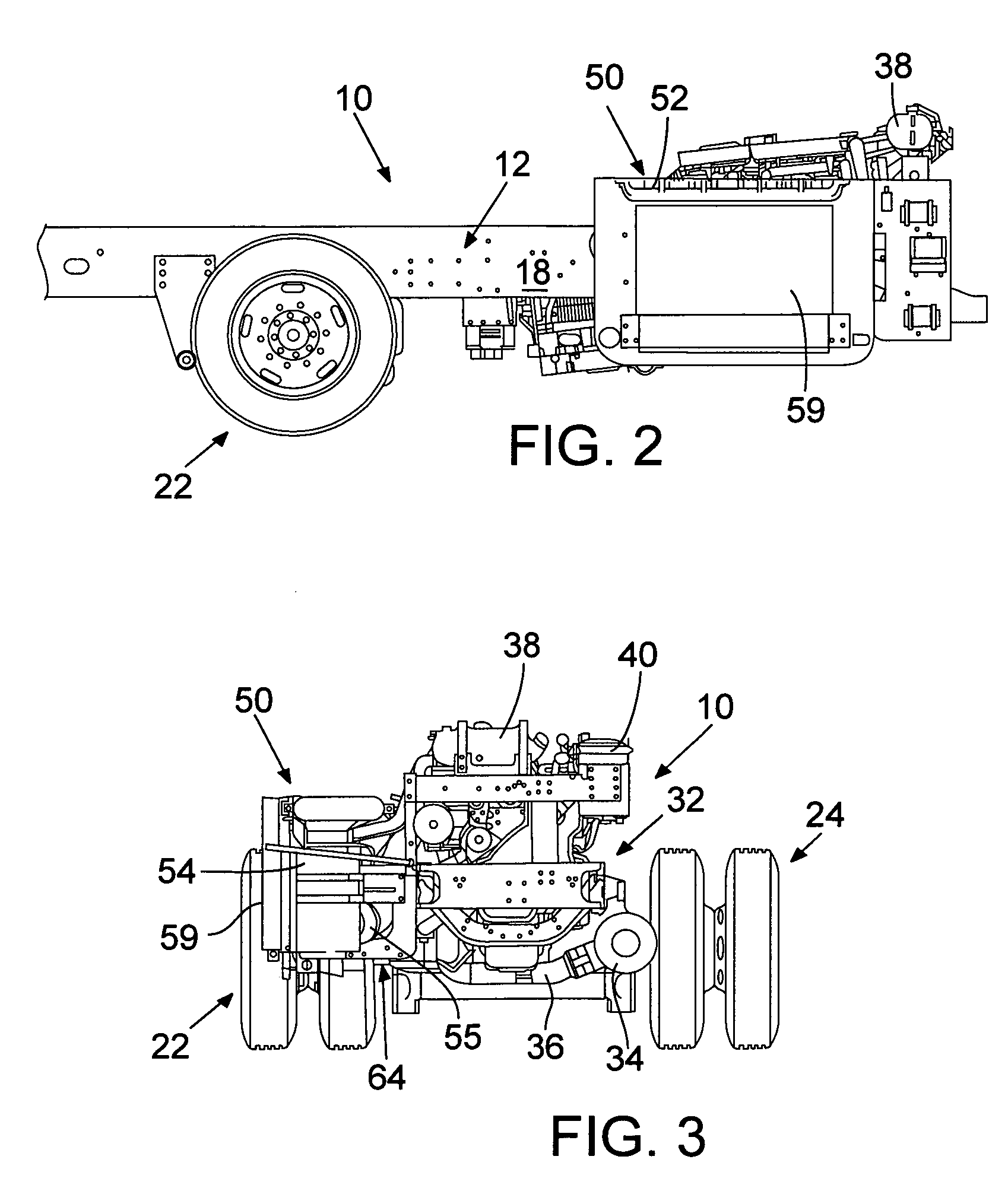
[0027]FIGS. 1, 2 and 3 illustrate one form of a chassis 10 of a vehicle. The portion of the chassis illustrated in FIGS. 1 and 2 comprises first and second spaced apart elongated frame rails 12,14 which are interconnected by cross-members such as cross-member 16 shown in FIG. 1. Frame rails may be an assembly of frame rail sections or formed of one piece. The term “frame rail member” includes one or both of a section of a frame rail as well as an entire frame rail. The frame rail may be straight or have other configurations. The illustrated frame rails 12,14 have respective outboard side surfaces 18,20. The frame rails may be, for example, of a C-shaped configuration with upper and lower inwardly projecting flanges and a side web.

[0028]The illustrated chassis 10 comprises rear wheels and tires 22,24 which are rotatably mounted to an axle 26 which is suspended from the frame rails 12,14 by a suspension 30. An engine 32 may also be carried by the frame rails. In FIG. 1, the engine is ...


PUM


Abstract

An elongated air intake plenum is disclosed together with mounting structure for supporting the plenum at the side of a vehicle chassis such as from the frame rail of a chassis for a motor home or recreational vehicle. The plenum and mounting structure is desirably positioned rearwardly of a rear axle of the chassis.

Description

RELATED APPLICATION DATA[0001]This application claims the benefit of U.S. provisional patent application No. 60 / 558,877, filed Apr. 2, 2004, entitled, “Vehicle Chassis With Side Mounted Air Intake Plenum”, by Nicholas Michael Rini and Mark Waitman Pitsenbarger, which is hereby incorporated by reference.TECHNICAL FIELD[0002]The technology disclosed herein relates to air intake plenums for vehicle engines and to chassis assemblies with such air intake plenums. The technology is particularly applicable to air intake plenums for rear engines of recreational vehicle chassis assemblies, such as for motor homes.BACKGROUND[0003]Air intake systems including air plenums for internal combustion engines are known. However, such systems suffer from a number of drawbacks such as difficulties in installation, inefficiencies in air delivery, and problems associated with the maintenance of such systems.[0004]Therefore, a need exists for improved air-intake plenums and for vehicle chassis with instal...

Claims


Application Information

Patent Timeline
IPC IPC(8): B60K11/00B60K13/02
CPCB60K13/02B60Y2200/143
Inventor RINI, NICHOLAS MICHAELPITSENBARGER, MARK WAITMAN
Owner DAIMLER TRUCKS NORTH AMERICA
Why Eureka
Try Eureka