Vehicle lamp

a technology for lamps and lamps, applied in the field of lamps for lamps, can solve the problems of increasing space and cost, increasing cost, and actuators not being used in common, and achieve the effects of cost reduction, cost reduction, and simplified support structure of lamps in relation to the housing

Active Publication Date: 2008-01-01
KOITO MFG CO LTD
View PDF12 Cites 19 Cited by
  • Summary
  • Abstract
  • Description
  • Claims
  • Application Information

AI Technical Summary

Benefits of technology

[0018]Further, in the vehicle lamp, the vehicle lamp may include a support shaft which is rotatable and tiltable with respect to a housing. The lamp unit is supported by the support shaft. The output part is coupled with the lamp unit at a portion on the opposite side to a portion where the lamp unit is coupled with the support shaft. The lamp unit is rotated around the support shaft, when the output part rotates, in the first drive mode. The lamp unit is tilted together with the support shaft, when the output part moves linearly in a direction substantially orthogonal to an axial direction of the support shaft, in the second drive mode. Therefore, the support structure of the lamp unit in relation to the housing is simplified, which contributes to cost reduction.
[0019]Further, in the vehicle lamp, the output part may be located on a vertical plane including an optical axis of the lamp unit. Therefore, the lamp units having the same structure can be used left and right, which contributes to the cost reduction.
[0021]When the two movable parts are moved in reversed phase, the output part rotates. When the two movable parts are moved in the same phase, the output part linearly moves. Therefore, the driving unit having the same structure can be used in the left and right lamp units, which contributes to the cost reduction.

Problems solved by technology

Therefore, the number of attachment steps of the actuator and the number of harnesses for power supply and control increase, which causes increases of space and cost.
Further, in the vehicle lamps provided right and left, the actuators cannot be used in common.
This point also causes the increase of cost.
In result, general-purpose properties are poor, and every time the lamp unit is different, a dedicated double axis actuator is required.
However, before one operation, for example, the horizontally rotational operation reaches a limit position, for example, before the lamp unit faces right in front, the tilting operation in the vertical direction cannot be performed.
Namely, the operations in the two different directions cannot be independently performed, and the other operation cannot be performed even in case that their operations are put in the any states.

Method used


Image

  • Vehicle lamp
  • Vehicle lamp
  • Vehicle lamp

Examples


Embodiment Construction

[0053]Exemplary embodiments of the invention will be described with reference to the accompanying drawings. In the exemplary embodiments, a vehicle lamp is applied to an automotive headlamp.

[0054]Firstly, referring to FIGS. 1 to 8, a first exemplary embodiment will be described.

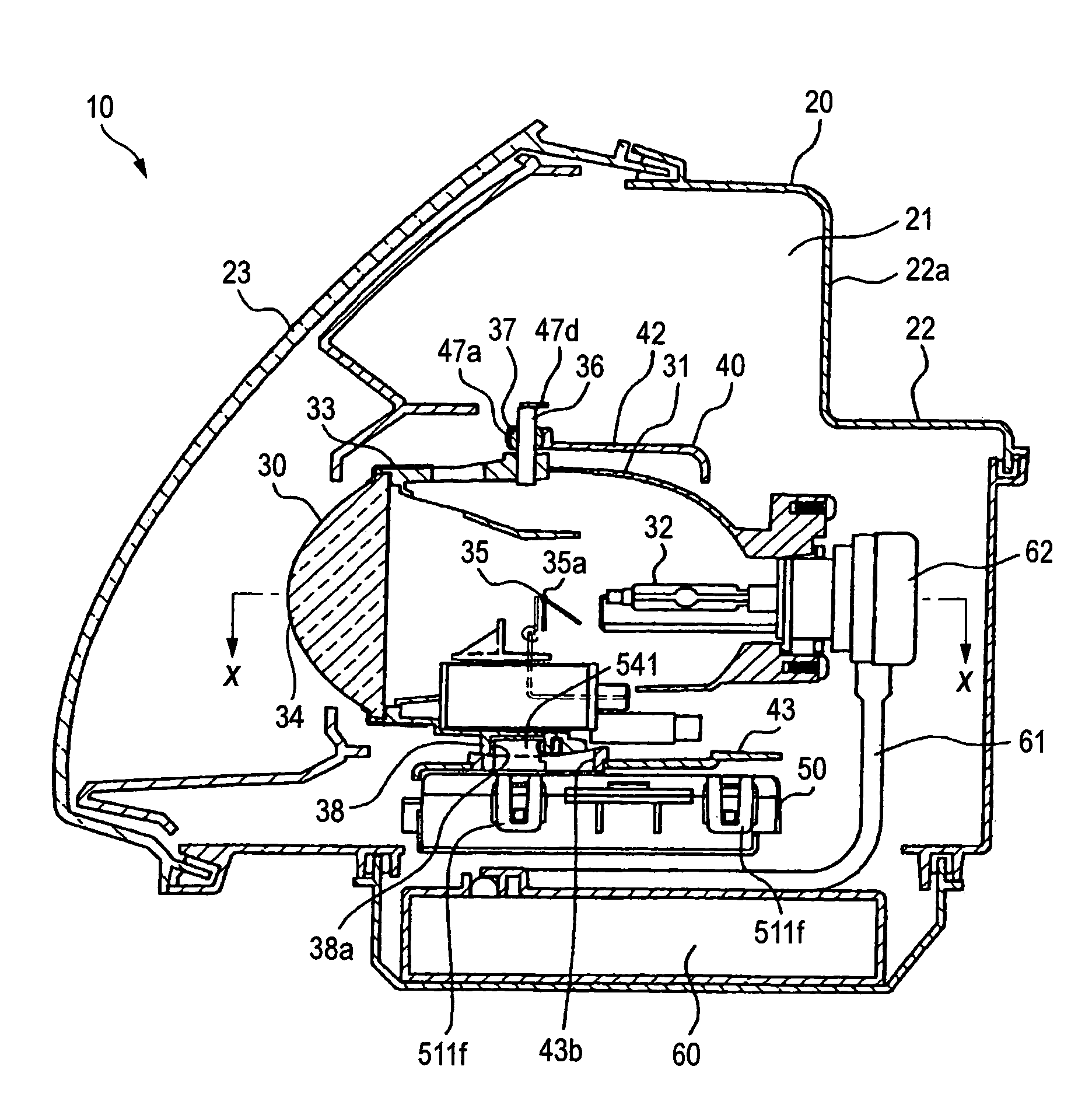
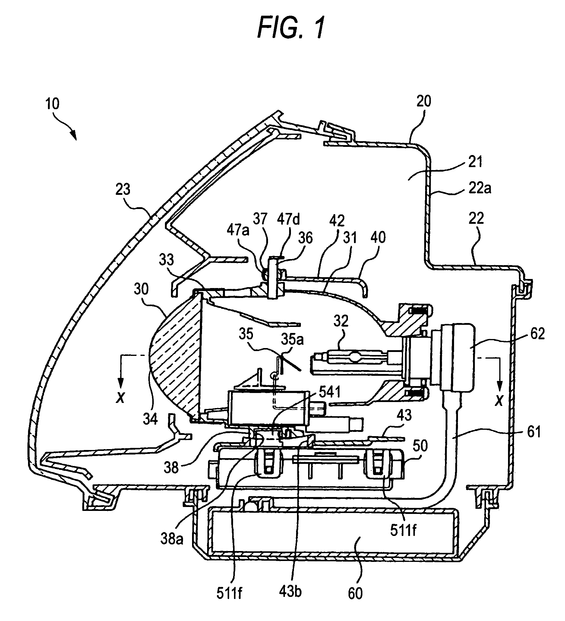
[0055]With reference to FIG. 1, an outline of an automotive headlamp will be described.

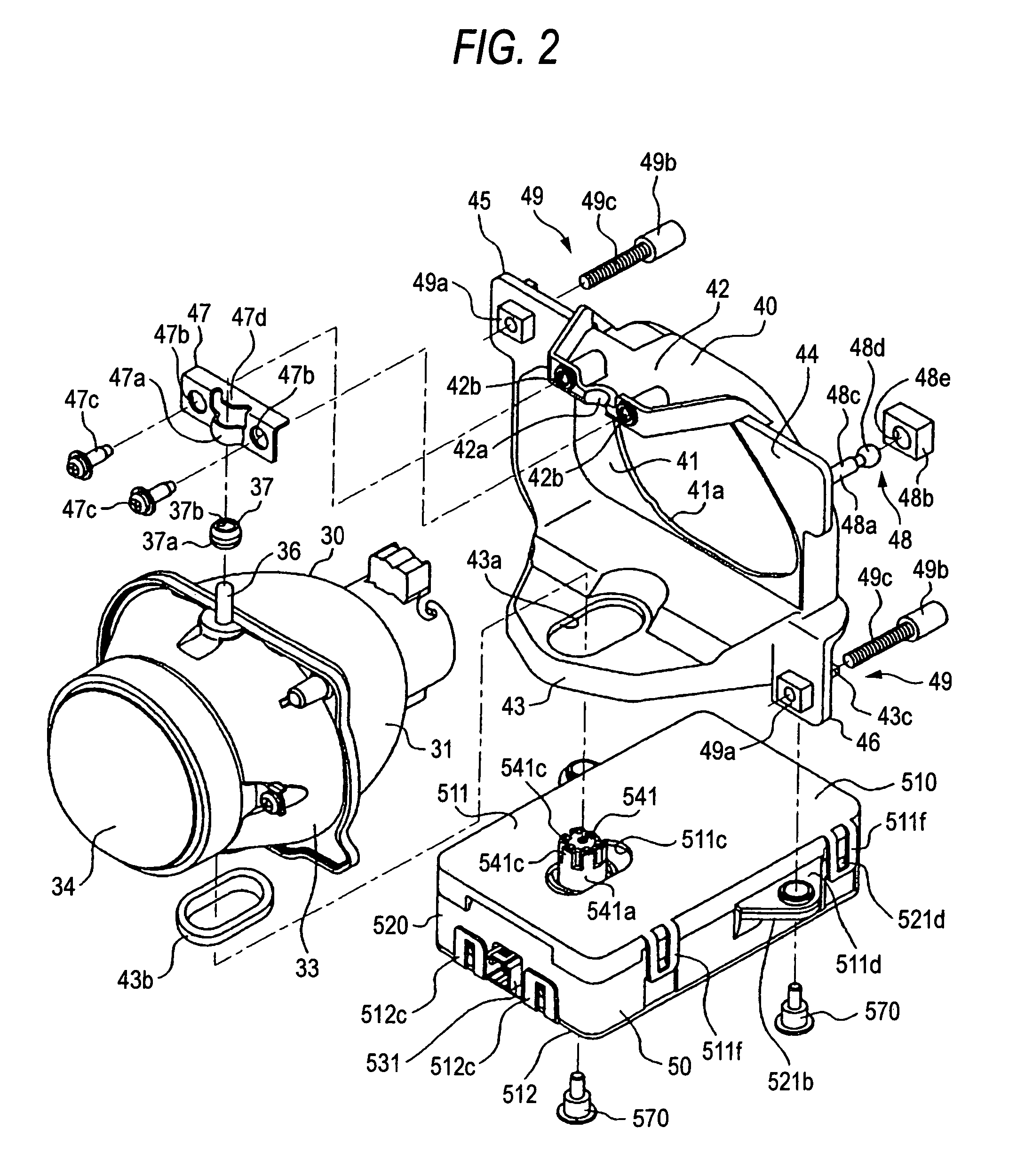
[0056]An automotive headlamp 10 includes a housing 20 having a lighting room 21 which is space that is closed nearly airtightly, and a lamp unit 30 which is arranged in the housing 20 rotatably in the vertical direction and in the right and left direction.

The housing 20 is unmoveably fixed to a vehicle body. In the housing 20, a front opening of a lamp body 22 having the shape of a container which opens forward is covered with a transparent cover 23.

[0057]In the shown automotive headlamp 10, the lamp unit 30 is supported through a bracket 40 by the lamp body 22 tiltably in the vertical direction and in the right and left di...


PUM


Abstract

A vehicle lamp 10 is provided with a lamp unit 30 which applies beams of the desired patterns ahead, and a double axis actuator 50 having a first drive mode in which the lamp unit is rotated in one of two planes that are orthogonal to each other and a second drive mode in which the lamp unit is rotated in the other of the two planes. The double axis actuator is provided with a single output part 540 which rotates the lamp unit in the two planes, and a drive part (including a drive source 550 and a movable part 561) which drives the output part. The double axis actuator can rotate the lamp unit in the each plane regardless of the rotational positions along the above two planes.

Description

[0001]This application claims foreign priority from Japanese Patent Application Nos. 2005-293563 filed on Oct. 6, 2005 and 2006-214553 filed on Aug. 7, 2006, the entire contents of which are hereby incorporated by reference.BACKGROUND OF THE INVENTION[0002]1. Field of the Invention[0003]The present invention relates to a vehicle lamp in which an irradiation direction is adjustable in a horizontal direction and a vertical direction that are orthogonal to each other.[0004]2. Related Art[0005]There is a vehicle lamp which can adjust an irradiation direction in a horizontal direction and in a vertical direction according to a running condition of the vehicle.[0006]For example, in an automotive headlamp, there is a case where the irradiation direction is too upward or too downward depending on a load. In such the case, it is necessary to change the irradiation direction in the downward direction or in the upward direction timely to correctly make the irradiation direction. Further, in ca...

Claims


Application Information

Patent Timeline
Patent Type & Authority Patents(United States)
IPC IPC(8): B60Q1/02B60Q1/00B60Q3/00F21W107/10F21Y101/00
CPCB60Q1/076B60Q1/04B60Q1/10
Inventor TAJIMA, KEIICHI
Owner KOITO MFG CO LTD
Why Eureka
Try Eureka