Device for tensioning and loosening of an endless conveyor belt which is guided over deflection means

a conveyor belt and belt tensioning technology, which is applied in the direction of conveyors, transportation and packaging, etc., can solve the problems of uneven displacement of the deflection roller, increased wear and tear of the conveyor belt, and unclean operation run, so as to facilitate the tensioning process

Inactive Publication Date: 2005-03-03
HABASIT AG
View PDF9 Cites 21 Cited by
  • Summary
  • Abstract
  • Description
  • Claims
  • Application Information

AI Technical Summary

Benefits of technology

[0013] Preferably the displacement means comprise two crank levers, which are connected via a crank axle such that they are not rotatable in relation to each other, and are each rotatably connected with a lever rod via a link, the lever rods for their part being connected with the displaceable deflection means. With such displacement means the deflection means to be displaced are automatically displaceable parallel, i.e. the same in the direction of travel of the conveyor belt left and right. In addition, it guarantees that the tensioning and loosening length can be repeatably maintained the same size. Such a design of the displacement me

Problems solved by technology

Such devices do not guarantee that the deflection roller is evenly displaced, i.e. the same in the direction of travel lef

Method used


Image

  • Device for tensioning and loosening of an endless conveyor belt which is guided over deflection means
  • Device for tensioning and loosening of an endless conveyor belt which is guided over deflection means
  • Device for tensioning and loosening of an endless conveyor belt which is guided over deflection means

Examples


first embodiment

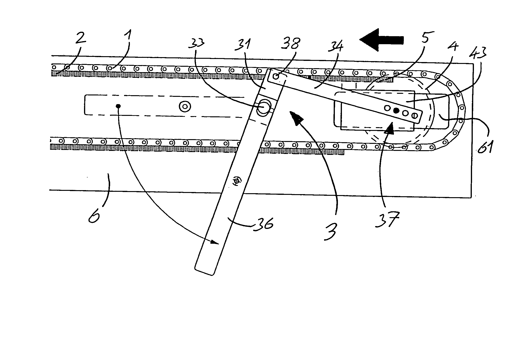
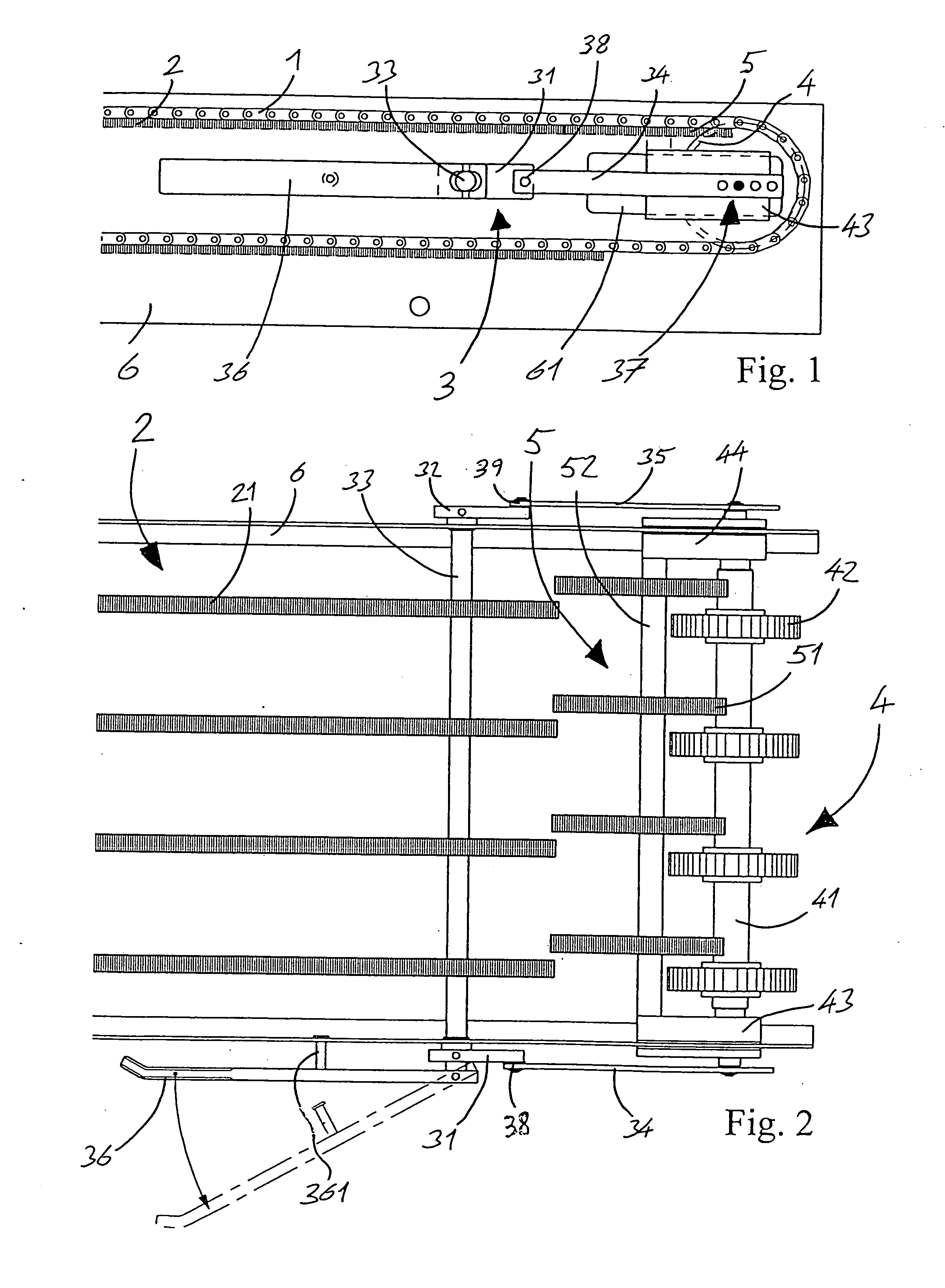
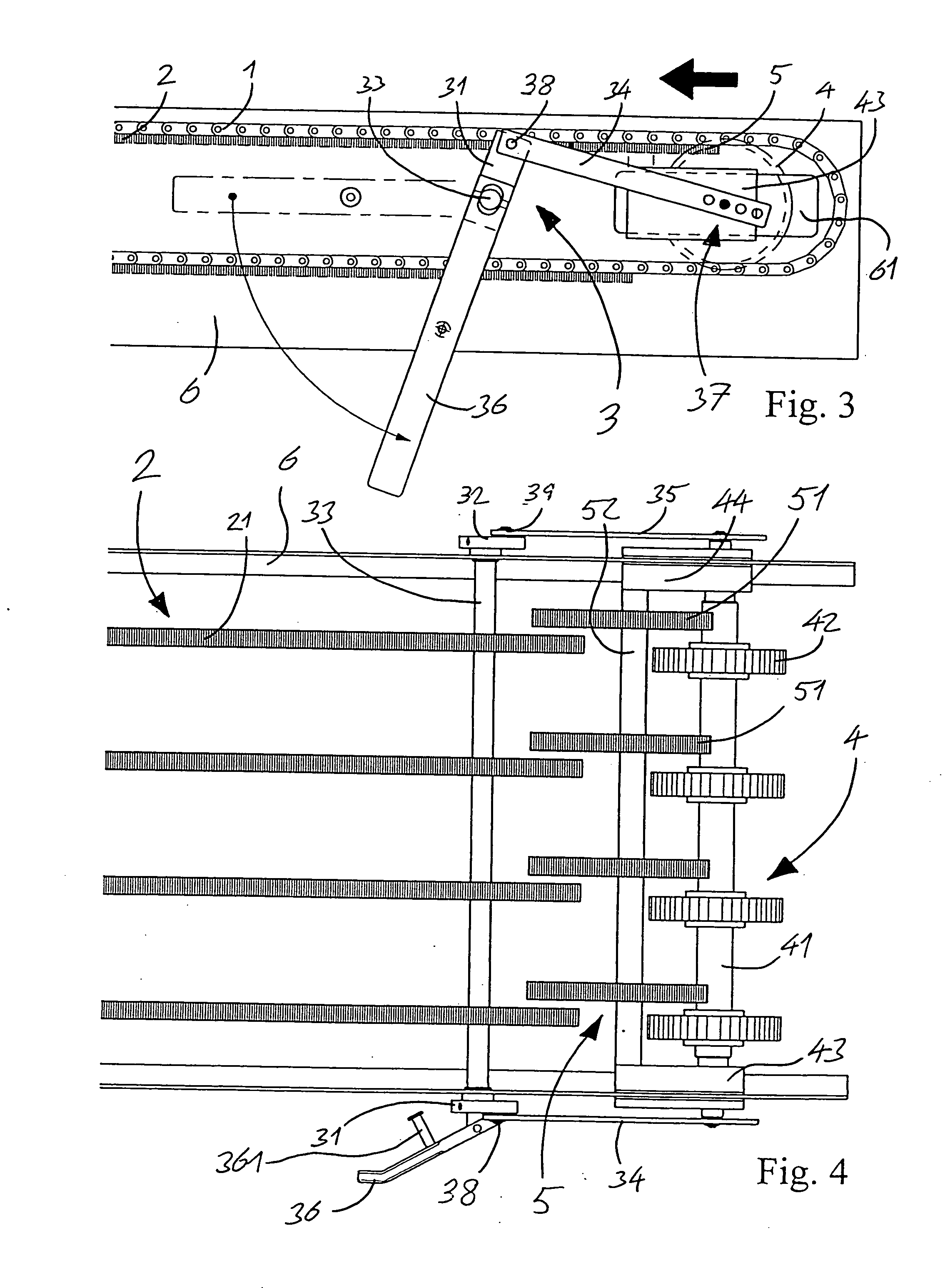
[0033] a conveyor belt conveying system with a device according to the invention in tensioned condition is shown in FIGS. 1 and 2. An endless conveyor belt 1 comprising synthetic members, is horizontally guided over a support construction 2, which comprises several sliding bars 21, which are spaced apart from each other and arranged in the direction of travel of the conveyor belt 1. At the end of the conveyor belt conveying system the conveyor belt 1 is diverted around 180° over displaceable deflection means 4. These comprise a deflection axle 41 and toothed deflection wheels 42, which are connected with the deflection axle 41. In operation the toothed deflection wheels 42 mesh with the teeth in gaps of the conveyor belt 1 and deflect these without slippage. The deflection axle 41 is positioned in deflection axle bearings 43, 44, which are each displaceably guided in a gap 61 in a frame 6 of the conveyor belt conveying system at a distance from the end of the support construction 2,...

third embodiment

[0044] The FIGS. 7 and 8 show a conveyor belt conveying system with a device according to the invention in tensioned condition, wherein the displacement means 103 comprise sprung-designed lever rods 134, 135. The lever rods 134, 135 comprise for this reason coil or pneumatic springs. In tensioned condition of the conveyor belt 1 an additional tension force works through the sprung lever rods 134, 135 on the displaceable deflection means 4 and with that on the conveyor belt 1. By means of sprung lever rods 134, 135 so arranged, a belt tension can be produced which guarantees operation of the conveyor belt 1 without slippage, also when no belt sagging is present. That can especially be an advantage for spatial ratios which do not permit sufficient belt sagging.

[0045] Otherwise what has been said for the first embodiment applies.

[0046] The FIGS. 9 and 10 show the device according to the FIGS. 7 and 8 in a loosened condition.

fourth embodiment

[0047] In the FIGS. 11 and 12 a fourth embodiment is depicted of a conveyor belt conveying system with a device according to the invention in tensioned or loosened condition respectively. For the automation of the operation of an operating lever 236 the displacement means 203 comprise a pneumatic drive 206 with cylinder 262 and in that displaceable piston. The piston is rotatably connected via a coupling element 261 with the operating lever 236, while the cylinder 262 is rotatably connected with the frame 6 of the conveyor belt conveying system. If the device is in tensioned condition, the pneumatic drive 206 is arranged in the longitudinal direction parallel to the conveyor belt 1 and is there in contracted condition. For loosening of the conveyor belt 1 the pneumatic cylinder 206 rotates the operating lever 236 around the crank axle 33.

[0048] For the above described devices according to the invention other constructional variants are realizable.


PUM


Abstract

A device for tensioning and loosening of an endless conveyor belt (1) which is guided over deflection means, is additionally supported between the deflection means by a support construction (2). The device comprises displacement means (3) which are used for displacing of displaceable deflection means (4) parallel to the direction of travel of the conveyor belt (1). In addition it comprises support means (5), which are co-displaceable with the displacing of the displaceable deflection means (4). In this way the support means (5) support the conveyor belt (1) between the support construction (2) and the displaceable deflection means (4) throughout. Thereby the conveyor belt (1) does not sag down in a gap between the support construction (2) and the displaceable deflection means (4).

Description

FIELD OF THE INVENTION [0001] The invention relates to a device for tensioning and loosening of an endless conveyor belt which is guided over deflection means. BACKGROUND OF THE INVENTION [0002] Such devices are, for example, used on endless conveyor belts made from synthetic material members of any width, for loosening these out of an operationally suitable slightly tensioned condition or for tensioning these into an operationally suitable condition. This occurs when the distance between two deflection rollers, over which the conveyor belt is guided, is reduced or enlarged. The loosened condition of the conveyor belt can facilitate different processes, such as, for example, maintenance work on the conveyor belt, in particular the cleaning. For this, a raising of the conveyor belt by means of a suitable aid can additionally be useful. [0003] Different solution attempts were already proposed in the past for loosening and stretching of endless conveyor belts. For example, in NL 900283...

Claims


Application Information

Patent Timeline
IPC IPC(8): B65G23/44
CPCB65G23/44
Inventor ISELI, HANSRUDOLF
Owner HABASIT AG
Why Eureka
Try Eureka