Tilting device for a chair

a tilting device and chair technology, applied in the field of tilting devices for chairs, can solve the problems of a plurality of parts and a general configuration that is complicated and cumbersome, and achieve the effect of simple assembly of the chair

Active Publication Date: 2014-11-18
TOPSTAR
View PDF19 Cites 20 Cited by
  • Summary
  • Abstract
  • Description
  • Claims
  • Application Information

AI Technical Summary

Benefits of technology

[0008]Preferably, the upper end of the gas spring is secured in the bulge by frictional connection. This means that no additional fastening devices are requir

Problems solved by technology

A disadvantage in connection with the known lilting devices for a chair is the

Method used


Image

  • Tilting device for a chair
  • Tilting device for a chair
  • Tilting device for a chair

Examples


Embodiment Construction

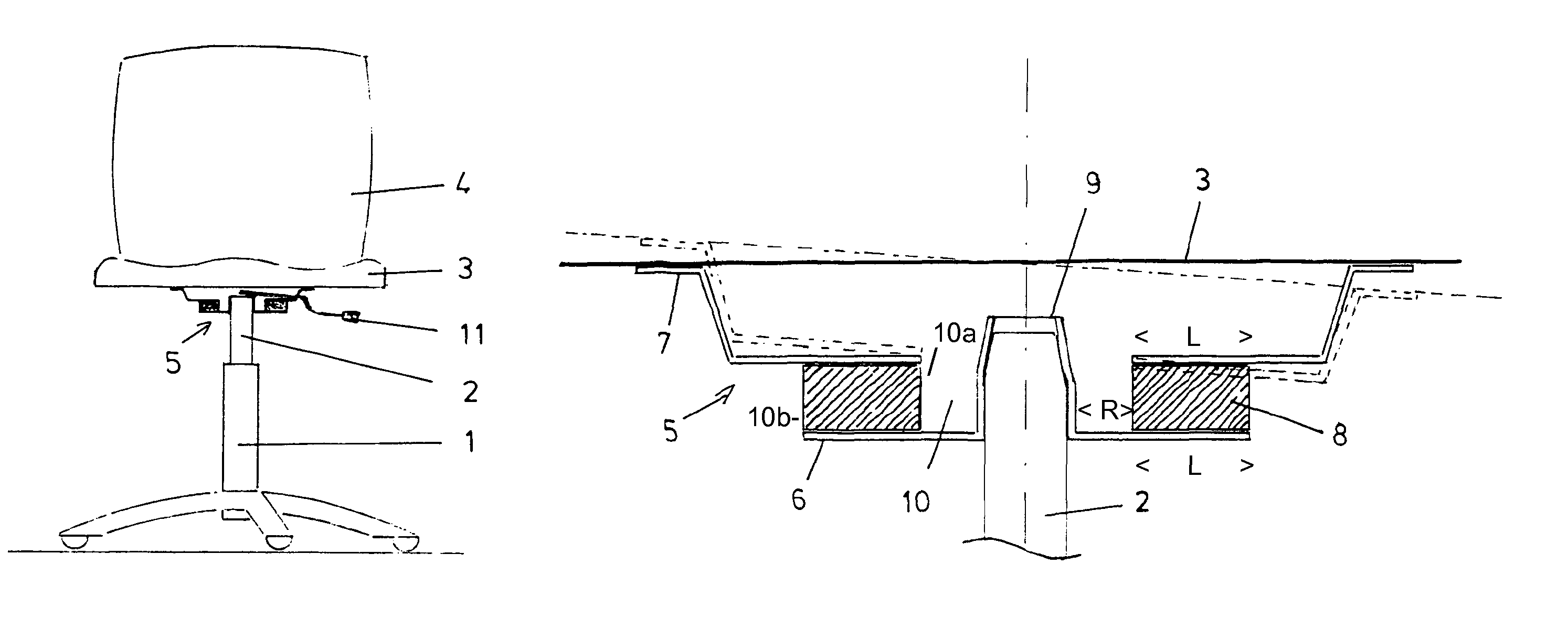
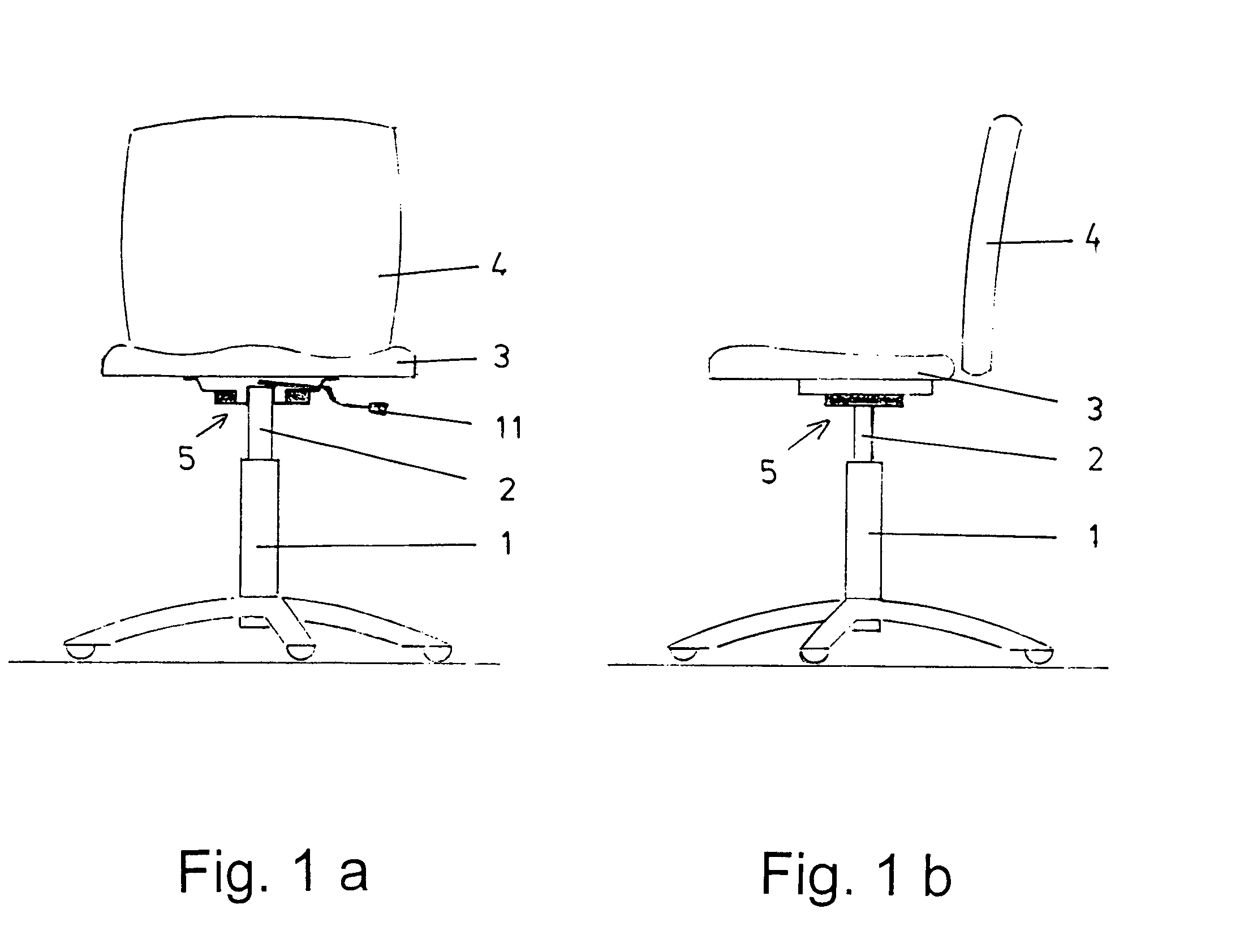
[0022]The chair that is illustrated in FIGS. 1a and 1b has a base 1. This base 1 has a gas spring 2 that extends vertically in upward direction.

[0023]Moreover, the chair has a seat plate 3. A backrest 4 is arranged thereat.

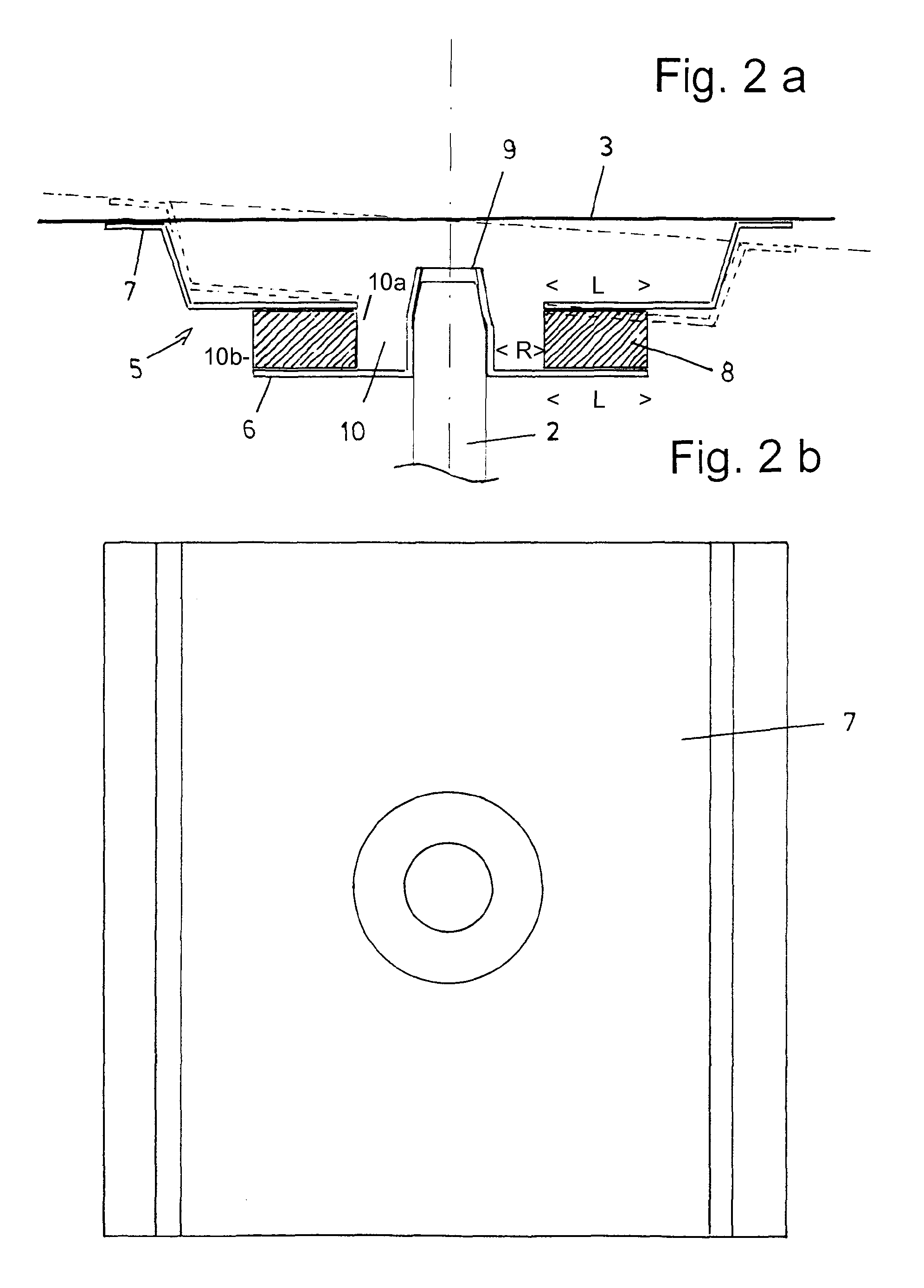
[0024]Between the base 1 and the seat plate 3 a tilting device 5 is arranged. This tilting device 5 is comprised of a bottom plate 6, a top plate 7 as well as an elastic body 8 that is positioned in a sandwich arrangement in between.

[0025]The bottom plate 6 has along the central axis a bulge 9 that extends vertically in upward direction. In the illustrated embodiment, it is initially cylindrically formed and tapers then in a conical shape in upward direction. The top plate 7 is arranged at a spacing above the bottom plate 6. Therebetween the elastic body 8 is arranged. The latter is connected with the two plates 6, 7 by vulcanization by plate sections of radial length L. However, it can also be glued, riveted or screwed to the two plates 6, 7. A fixation by positi...


PUM


Abstract

The invention relates to a tilting device (5) for a chair, comprising a lower plate (6) and an upper plate (7). An elastic body (8) is located therebetween. The lower plate (6) has a bulge (9) in the vertical direction, by means of which the tilting device (5) is placed onto the upper end of a gas spring (2). The seat plate (3) of the chair is fastened to the upper plate (7).

Description

BACKGROUND OF THE INVENTION[0001]The invention concerns a tilting device for a chair wherein the chair has a base with a gas spring that extends vertically in upward direction as well as a seat plate and wherein the tilting device, arranged between the base and the seat plate, comprises an elastic body that at the bottom side as well as the top side is fixedly connected to a rigid plate.[0002]Chairs that enable a tilting movement of the seat plate about a pivot point that is located within a central seat area are known in various embodiments. The basic principle resides always in that, on the bottom side of the seat plate, a support is arranged by using an elastic body. This elastic body counteracts the tilting movement with an appropriate restoring force.[0003]A disadvantage in connection with the known lilting devices for a chair is the generally very complex and complicated configuration with a plurality of parts.[0004]Based on this, the invention has the object to provide a tech...

Claims


Application Information

Patent Timeline
IPC IPC(8): A47C7/14A47C3/026A47C1/024A47C1/032A47C3/02A47C3/025A47C7/44
CPCA47C7/448A47C3/026A47C7/14A47C3/0252A47C1/03255
Inventor MEYER, STEFANWAGNER, PETER
Owner TOPSTAR
Why Eureka
Try Eureka