Lighting device for vehicle

a vehicle and lighting technology, applied in the direction of lighting support devices, lighting and heating apparatus, instruments, etc., can solve the problems of increasing the cost of components, increasing the required man-hours for assembly, increasing the number of components, etc., to reduce the cost and size, simplify the support of the lamp unit, and reduce the number of components

Inactive Publication Date: 2008-05-15
KOITO MFG CO LTD
View PDF10 Cites 22 Cited by
  • Summary
  • Abstract
  • Description
  • Claims
  • Application Information

AI Technical Summary

Benefits of technology

[0008]In one or more embodiments of the present invention, a support of a lamp unit is simplified and the number of components is decreased, thereby reducing cost and size.

Problems solved by technology

For these reasons, the number of components is increased and cost is necessarily increased with an increase in a component cost and an increase in the required man-hours for assembly.

Method used


Image

  • Lighting device for vehicle
  • Lighting device for vehicle
  • Lighting device for vehicle

Examples


first embodiment

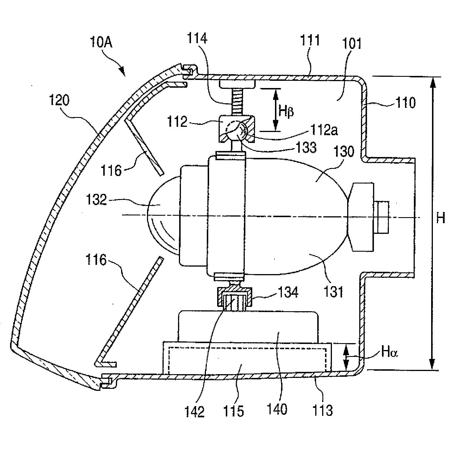
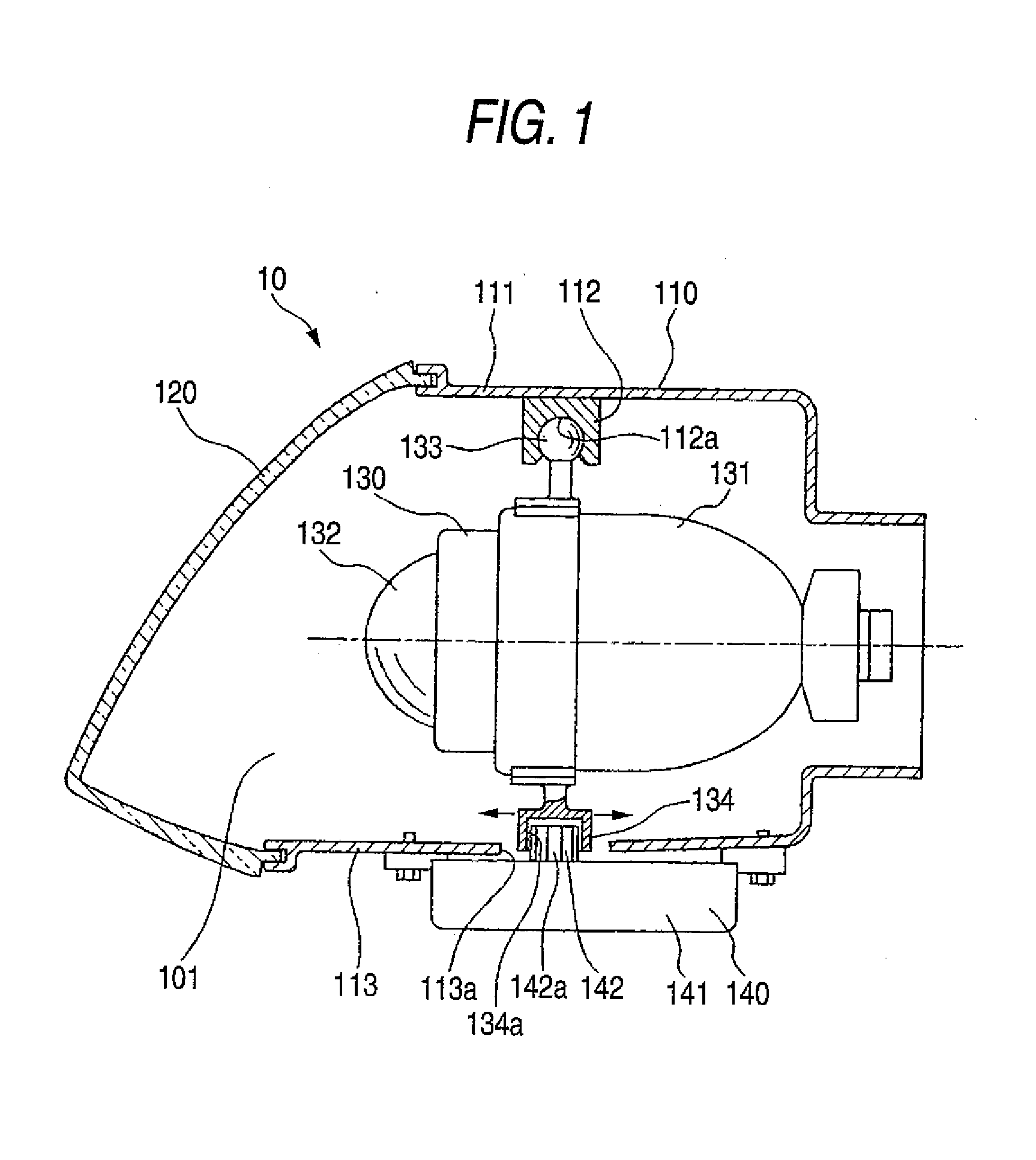
[0032]FIG. 1 shows a schematic of a headlamp for a car according to the invention.

[0033]A headlamp 10 for a car includes a lamp body 110 having a concave portion opened forward, and the front opening of the lamp body 10 is covered with a transparent cover 120 so that a lamp housing 101 is formed. A lamp unit 130 is supported in the lamp housing 101 tiltably in vertical and transverse directions. Furthermore, an actuator 140 for tilting the lamp unit 130 in the transverse direction is disposed in the lamp housing 101.

[0034]The lamp unit 130 includes, at least, a reflector 131, a projection lens 132 and a light source which is not shown, and serves to irradiate an illumination light forward. A body coupling portion 133 to be coupled to the lamp body 110 is formed on an upper end of the lamp unit 130, and, furthermore, an actuator coupling portion 134 to be coupled to the actuator is formed on a lower end of the lamp unit 130. In the embodiment shown, the body coupling portion 133 is f...

second embodiment

[0057]FIGS. 6 to 9 show the actuator.

[0058]An actuator 20 has an output shaft 220 protruded upward from a case 210, and the output shaft 220 is rotated around an axis extended in an almost vertical direction and is provided movably in a longitudinal direction. A rotation driving mechanism 230 for rotating the output shaft 220 around an axis extended in an almost vertical direction and a horizontal driving mechanism 240 for moving the output shaft 220 in the longitudinal direction are constituted in the case 210.

[0059]The output shaft 220 takes an almost cylindrical shape and has a central hole 221 penetrating through a center. Moreover, engaging convex bars 222, 222, . . . extended in an axial direction are protruded from an almost upper half part of an outer peripheral surface of the output shaft 220. Moreover, a gear tooth is formed in an almost lower half part of the outer peripheral surface of the output shaft 220 and is set to be a wheel gear portion 231.

[0060]A slider 241 is p...

third embodiment

[0077]FIG. 10 shows the actuator.

[0078]An actuator 60 according to the third embodiment is different from the actuator 20 according to the second embodiment in that a leveling driving portion 30 is not provided. More specifically, in the actuator 60, a horizontal driving shaft 610 and a support structure thereof are different from the horizontal driving shaft 242 of the actuator 20 and the other portions are the same as in the actuator20. Accordingly, only the difference will be described in detail, and the other portions have the same reference numerals as those in the actuator 20 and description will be omitted.

[0079]The horizontal driving shaft 610 is constituted by a screw shaft portion 611 having a screw bar formed on an outer peripheral surface and a coupling portion 612 formed integrally with a rear end of the screw shaft portion 611. The coupling portion 612 is provided with a coupling hole 612a having a rectangular section. The horizontal driving shaft 610 is supported on a...


PUM


Abstract

A lighting device for a vehicle includes a lamp unit serving to irradiate a light forward, and an actuator having a single output shaft for tilting the lamp unit vertically and transversely. The lamp unit is disposed in a lamp housing formed by a lamp body and a transparent cover for covering a front surface of the lamp body. The lamp unit includes a body coupling portion to be coupled to the lamp body and an actuator coupling portion to be coupled to the actuator. The lamp body includes a lamp unit coupling portion coupled to the body coupling portion and serving to support the lamp unit tiltably in vertical and transverse directions. The actuator is supported on the lamp body and includes an output shaft for tilting the lamp unit vertically and transversely in engagement with the actuator coupling portion of the lamp unit.

Description

[0001]This application claims foreign priority from Japanese Patent Application No. 2006-306787 filed on Nov. 13, 2006, the entire contents of which are hereby incorporated by reference.BACKGROUND OF THE INVENTION[0002]1. Field of the Invention[0003]The present invention relates to a novel lighting device for a vehicle. More specifically, the invention relates to a technique for simplifying a support of a lamp unit and decreasing the number of components, thereby reducing cost and size.[0004]2. Related Art[0005]Some lighting devices for a vehicle, for example, some headlamps for a car can change an irradiating direction into vertically and transversely optional directions.[0006]In a lighting device for a vehicle described in Patent Document 1, a lamp unit is supported on a bracket transversely tiltable and the bracket is supported on a vertically tiltable lamp body, and the transverse tilt of the lamp unit and the vertical tilt of the bracket are carried out using separate driving d...

Claims


Application Information

Patent Timeline
Patent Type & Authority Applications(United States)
IPC IPC(8): F21V14/02F21V7/00F21S8/10F21Y101/00
CPCB60Q1/072B60Q2200/38B60Q2200/32B60Q1/076
Inventor TATARA, NAOHISAKUSAGAYA, MASAHIRO
Owner KOITO MFG CO LTD
Why Eureka
Try Eureka