
Positioning system with intentional multi-path signal

a multi-path signal and positioning system technology, applied in the field of positioning systems, can solve the problems of low accuracy, laser systems currently employ expensive pointing mechanisms, and acoustic systems can only measure the range to accuracies of a centimeter or more, and achieve the effect of high accuracy

Active Publication Date: 2008-01-01
DEERE & CO
View PDF45 Cites 16 Cited by
  • Summary
  • Abstract
  • Description
  • Claims
  • Application Information

AI Technical Summary

Problems solved by technology

Global positioning systems such as GPS provide only medium accuracy position information, usually no better than 10 cm, and require a clear view of the sky to near the horizon.
Unfortunately, because of the properties of sound propagation through air, acoustic systems can only measure range to accuracies of a centimeter or more, and only over relatively short distances.
However, laser systems currently employ expensive pointing mechanisms that can drive the system cost to $30K or more.

Method used


Image

  • Positioning system with intentional multi-path signal
  • Positioning system with intentional multi-path signal
  • Positioning system with intentional multi-path signal

Examples


embodiment 100

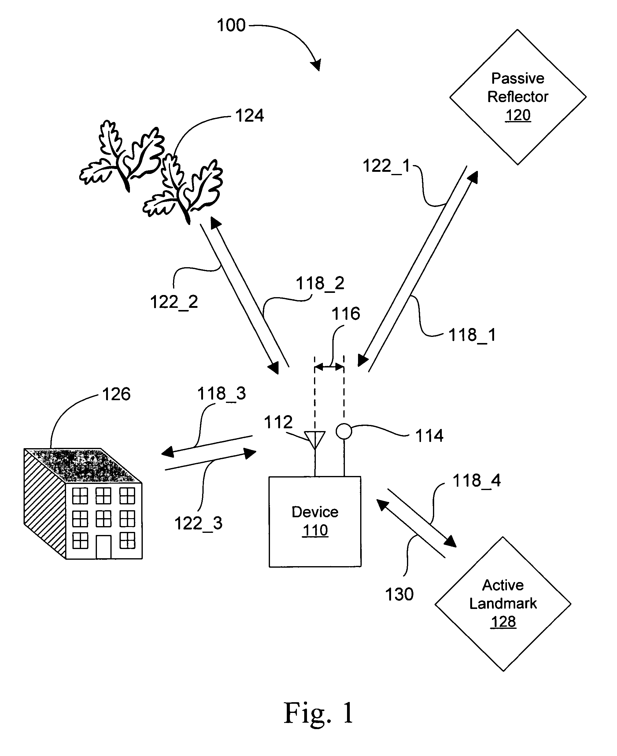
[0027]FIG. 1 illustrates an embodiment 100 of the positioning system with one or more intentional multi-path signals. A device 110 is configured to transmit one or more signals 118, each of which includes at least one electromagnetic pulse having a carrier signal frequency, using at least one antenna 112. In some embodiments, the device 110 is configured to transmit one or more signals 118 having a plurality of electromagnetic pulses. In an exemplary embodiment, the pulses are 1 nanosecond (ns) in duration and have the carrier signal frequency of 6 gigahertz (GHz). A typical repetition period for the pulses is every microsecond. Other embodiments may employ pulse duration and carrier signal frequency pairings of: 1 ns and 24 GHz; 5 ns and 6 GHz; and 1 ns and 77 GHz. The increased accuracy of range estimation available from shorter pulse durations and higher carrier signal frequencies comes at the expense of increased cost and complexity of associated circuitry in some embodiments.

[0...

embodiment 200

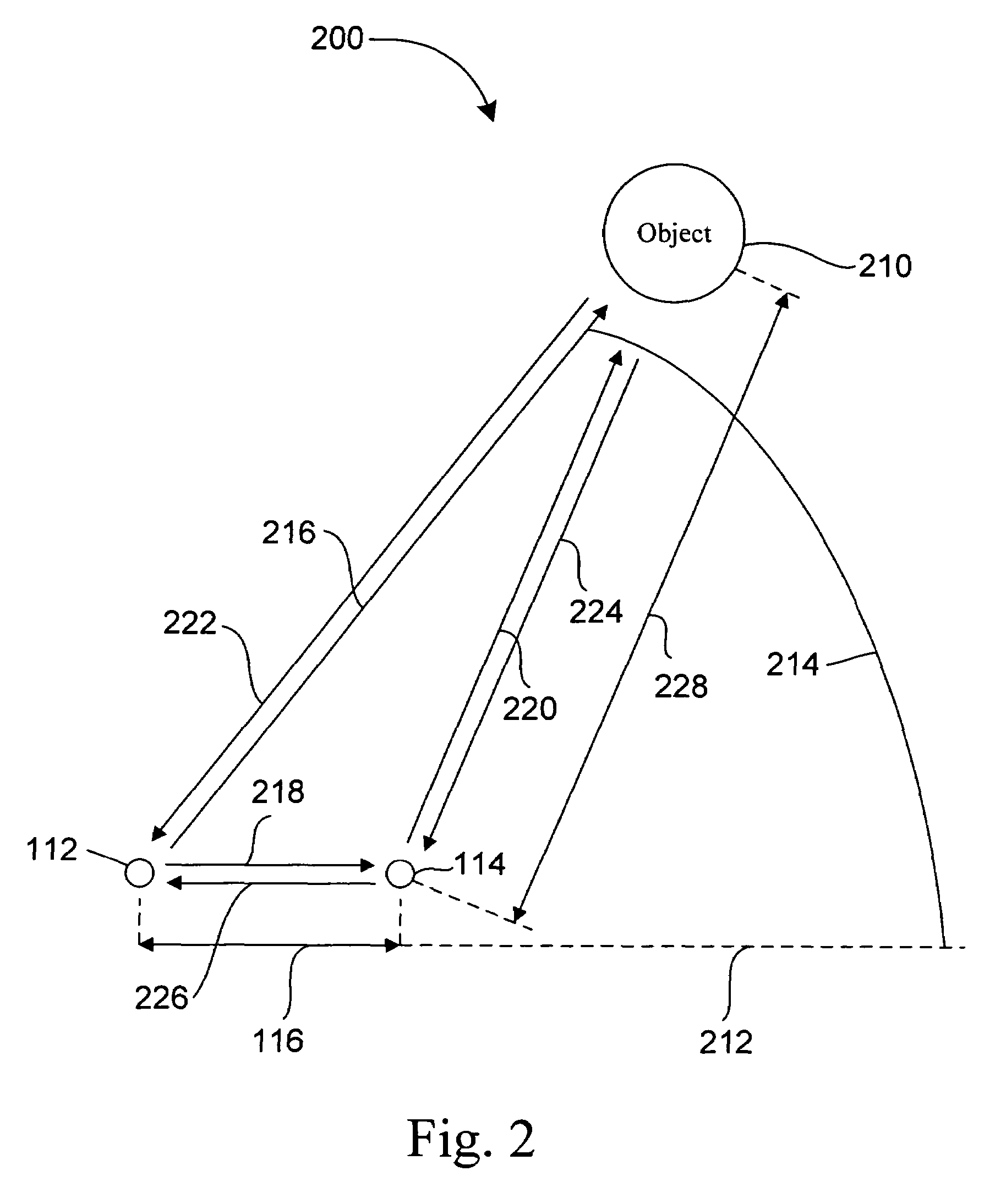
[0039]FIG. 2 illustrates an embodiment 200 of the positioning system with one or more intentional multi-path signals. Object 210 is at the position with an angle 214 with respect to a line 212 and a direction, such as direction 216, between the antenna 112 (and thus the device 110 in FIG. 1) and the object 210. The antenna 112 transmits a direct-path signal, including at least one electromagnetic pulse having the carrier signal frequency, along the direction 216. The antenna also transmits a signal, including at least one electromagnetic pulse having the carrier signal frequency, along direction 218. The reflector 114 will reflect a first return multi-path signal, including at least one electromagnetic multi-path pulse, along direction 226. A total propagation time for this first return multi-path signal is sufficiently short that, for purposes of determining the position of the object 210, the first return multi-path pulse may be ignored. The reflector 114 will also reflect a multi...


PUM


Abstract

A positioning system includes a device, having an antenna and a reflector with a known position proximate to the antenna, that transmits at least an electromagnetic pulse having a carrier signal frequency. The device receives a return signal over a period of time, wherein the return signal includes a return pulse from an object within a radar detection area of the device and at least one multi-path pulse. The device processes the return signal so as to isolate the return pulse and the at least one multi-path pulse from the return signal. The device determines a range from the device to the object and the position of the device relative to the object. The range is determined in accordance with a time of arrival of the return pulse and the position is determined in accordance with a time of arrival of the at least one multi-path pulse.

Description

[0001]This application is a continuation-in-part of U.S. patent application Ser. No. 10 / 614,097, filed Jul. 3, 2003 now U.S. Pat. No. 7,250,901, which is hereby incorporated by reference in its entirety.FIELD OF THE INVENTION[0002]The present invention relates generally to positioning systems and more specifically, to a system and method for determining the position of a mobile device relative to a number of objects using one or more intentional multi-path signals.BACKGROUND OF THE INVENTION[0003]Local positioning systems are becoming an important enabler in mobile devices requiring navigation capabilities, especially in applications of autonomous vehicles and precision construction tools. Global positioning systems such as GPS provide only medium accuracy position information, usually no better than 10 cm, and require a clear view of the sky to near the horizon. Local positioning systems, with either active or passive components distributed in a working volume, can allow much more ...

Claims


Application Information

Patent Timeline
Patent Type & Authority Patents(United States)
IPC IPC(8): G01S13/08H01Q15/00G01S5/02G01S7/02G01S13/18G01S13/75G01S13/87
CPCG01S3/72G01S5/14G01S7/026G01S13/4418G01S13/449G01S13/876G01S5/0273G01S13/75G01S2007/4078G01S2013/466G01S2013/468G01S7/4078
Inventor STEPHENS, SCOTT ADAM
Owner DEERE & CO
Learn More