Hair brush including hair removal means

a hair brush and hair technology, applied in the field of hair brushes, can solve the problems of requiring a considerable amount of force to be applied to remove the cleaning plate, the arrangement is not as easy to use as is desired, and the prior art arrangement is relatively complex and expensive to manufacture, so as to facilitate the repositioning of the frame engaging surface and facilitate the removal of hair

Inactive Publication Date: 2008-01-08
KOKE ERIC JOHN
View PDF14 Cites 30 Cited by
  • Summary
  • Abstract
  • Description
  • Claims
  • Application Information

AI Technical Summary

Benefits of technology

[0010]The bristle retaining plate is secured to the frame with the arcuate frame engaging major surface thereof disposed in juxtaposition with the arcuate surface portion of the frame. The bristle retaining plate can be disengaged from the frame to facilitate removal of hair from the plate and bristles. When the plate is disengaged from the frame, the bristles may slide through the corresponding holes in the bristle retaining plate until the bulbous ends engage the upper major surface of the bristle retaining plate, and may also slide through the corresponding holes in the bristle retaining plate until the frame engaging ends engage the corresponding holes in the bristle retaining plate so as to facilitate re-positioning of the frame engaging surface of the bristle retaining plate in juxtaposition with the arcuate portion of the brush frame.

Problems solved by technology

Such prior art arrangements are relatively complex and expensive to manufacture, and are susceptible to jamming and other mechanical malfunctions.
However, this arrangement is not as easy to use as is desired, and requires a considerable amount of force to be applied to remove the cleaning plate.
It is not suitable for making a hair brush with bristles which are not all parallel to each other, but which extend outward in a generally radial manner, as if preferred by most users of hair brushes.

Method used


Image

  • Hair brush including hair removal means
  • Hair brush including hair removal means
  • Hair brush including hair removal means

Examples


Embodiment Construction

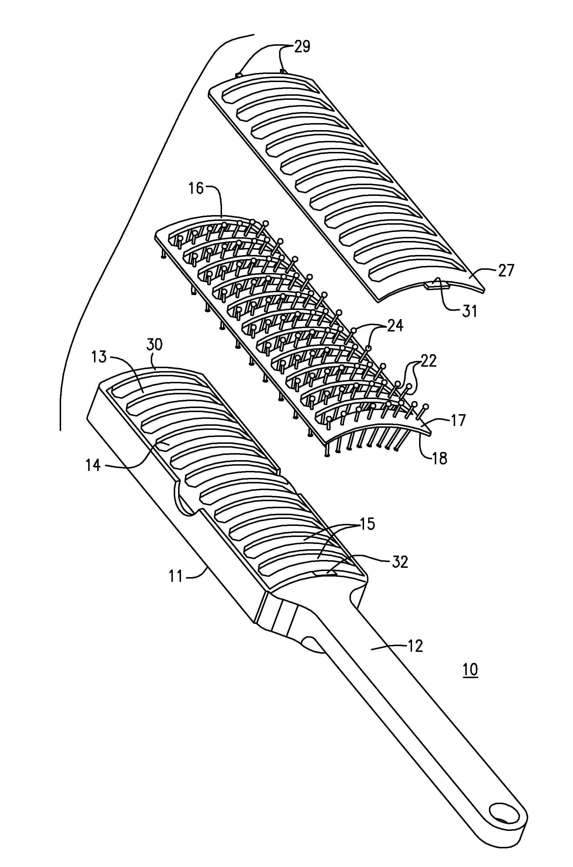
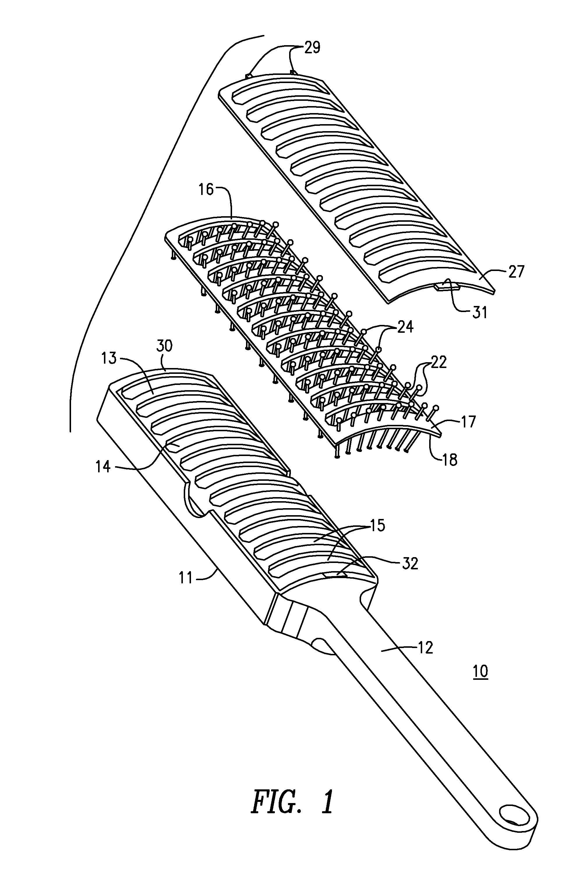
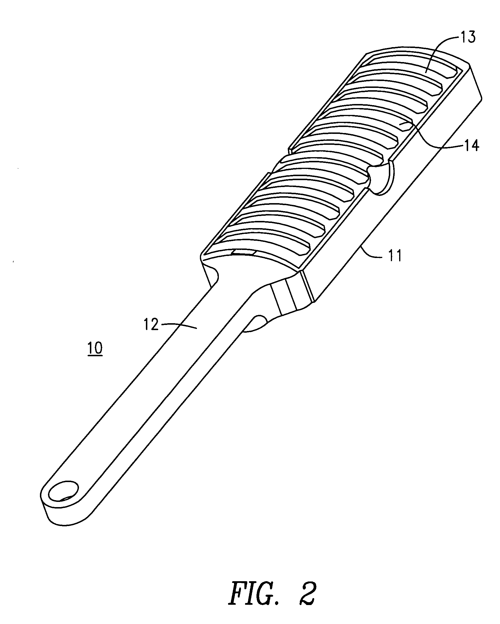
[0045]As seen inFIGS. 1, 4 and 6, the hair brush 10 has a body portion 11 and a handle 12. The body portion 11 has a recess 13, the bottom surface 14 of which has a curved or arcuate generally convex shape. A series of parallel slots or vents 15 extends between the major surfaces of the recess 13.

[0046]A bristle retaining plate 16 has an arcuate shape conforming to the shape of the bottom surface 14 of the recess 13, an upper major surface 17 and a lower or frame recess engaging surface 18 which rests on and contacts the convex bottom surface 14 of the recess 13.

[0047]A multiplicity of bristle receiving holes 19 extends between the bristle retaining plate major surfaces 17 and 18. At the bottom surface 18 of the bristle retaining plate 16 the holes 19 have chamfers 20. At the upper surface 17 of the plate, the holes are surrounded by lands 21 which help to maintain bristles disposed in the holes, in an orientation perpendicular to the plate major surfaces.

[0048]Disposed in each of t...


PUM


Abstract

A hair brush having a handle and a body portion with a recess having a convex bottom surface. A similarly curved bristle retaining plate has bristle retaining holes with one bristle slidably installed in each hole. Each bristle has an enlarged bulbous upper end and a wedge-shaped lower end so that it can slide through the bristle retaining plate between its ends. The holes have chamfers at the bottom surface of the plate, and the wedge-shaped ends of the bristles are dimensioned so as to fit in the chamfers. A similarly curved hair removal plate with bristle receiving holes is placed atop the bristle retaining plate, and detachably retained in position. To clean the brush, the hair removal plate is removed from the bristle retaining plate, and the bristle retaining plate is removed from the recess and turned to cause the bristles to slide in the holes so that their bulbous ends contact the bristle retaining plate. Thereafter the plates are returned to their original positions. In a second embodiment the bristle retaining plate may be hinged to the body portion of the brush at one end of the recess, and latched to the body portion at the opposite end of the recess; and the hair removal plate is not used.

Description

CROSS-REFERENCE TO RELATED APPLICATION[0001]This application claims the benefit of U.S. Provisional Application Ser. No. 60 / 485,788 filed Jul. 10, 2003 and entitled Superclean Hair Brush.BACKGROUND OF THE INVENTION[0002]This invention relates to a hair brush of the type having a member slidably moveable along the bristles thereof, for the purpose of cleaning the brush by removing hair therefrom.[0003]Hair brushes of this type, for use on both humans and animals, are well known in the art. Such brushes are exemplified by U.S. Pat. No. 5,600,865 to Morrison; U.S. Pat. No. 4,517,703 to the inventor in the present application, U.S. Pat. No. 2,529,927 to Fisk; U.S. Pat. No. 3,108,305 to Peilet; U.S. Pat. No. 3,110,053 to Surabian; U.S. Pat. No. 1,290,554 to Healey; U.S. Pat. No. 1,050,103 to Clemens; and U.S. Pat. No. 1,164,204 to Mullett et al.[0004]In the arrangement of Fisk a foraminous cleaning plate 11 has holes through which the bristles extend. The cleaning plate is slidably movab...

Claims


Application Information

Patent Timeline
Patent Type & Authority Patents(United States)
IPC IPC(8): A46B17/06A45D24/42
CPCA46B17/06A45D24/42A46B2200/104
Inventor KOKE, ERIC JOHN
Owner KOKE ERIC JOHN
Why Eureka
Try Eureka