License-plate frame bumper guard

a bumper guard and license plate technology, applied in the direction of bumpers, display means, instruments, etc., can solve the problems of bumper damage, bumper damage, bumper damage, etc., and achieve the effect of repairing or replacing the bumper, and requiring substantial work and/or expense to attach or apply

Active Publication Date: 2008-01-08
LEVINE JEFFREY K
View PDF3 Cites 19 Cited by
  • Summary
  • Abstract
  • Description
  • Claims
  • Application Information

AI Technical Summary

Benefits of technology

[0005]The fastening device used to mount the bumper guard to the vehicle may be, and preferably is, the same fastening device used to mount the license-plate to the bumper guard; for example, bolts extend through recesses in the license-plate and aligned recesses in the bumper guard to be received in recesses in the vehicle license plate fixture for mounting both the license-plate and the bumper guard to the vehicle. Alternatively, bolts or studs extend from the mounting area or fixture and the license plate and bumper-guard are fastened to the bolts or studs with suitable nuts. In the alternative the license-plate can be separately mounted to the bumper guard and the bumper-guard separately mounted to the vehicle; for example, first screws extend through recesses in the bumper guard to be received in the license plate mounting fixture recesses for mounting the bumper guard to the vehicle while second fastening devices, such as screws or clips, extend through the license-plate recesses and attach to the bumper guard for mounting the license-plate to the bumper guard. One beneficial application associated with the use of separate fasteners is, for example, a car dealer can exchange dealer plates between various cars without having to remove the license-plate from the bumper guard by simply attaching and detaching the bumper guard with the license-plate remaining connected thereto.
[0006]Furthermore, a bumper guard having a mounting plate similarly sized to the dimensions of a license-plate and having recesses configured to align with the preexisting fasteners, e.g., screw receiving recesses or studs, located at the license-plate mounting or fixture area would be capable of easily mounting to many types of bumpers or vehicle body work despite the shape of the surrounding bumper or body portion. Accordingly, this allows one to avoid ordering a custom bumper guard particularly designed to accommodate a certain vehicle's bumper or body shape, and allows generic use of a bumper guard with varying bumper and body designs.
[0007]Even further, should the bumper guard itself become scratched, nicked or bent it is easily removable by removing it from the preexisting vehicle fixture and placing another guard in its place. Placing a removable or non-removable cover such as foam and / or rubber over a portion of the bumper guard creates a soft exterior so that scratches and other such damage to another vehicle are not easily caused by contacting the guard. Also, such a cover creates a repairable / replaceable surface for maintaining a clean appearance.
[0009]It is a further object of the present invention to provide a bumper guard mountable to the preexisting license-plate mounting fixture that is capable of accommodating a license-plate without obstructing the visibility thereof.
[0012]A further object of the present invention is to provide a removable or non-removable cover such as foam and / or rubber over a portion of the bumper guard of the present invention to maintain a soft exterior, protect its surface from scratches and maintain a neat appearance with a repairable / replaceable surface.

Problems solved by technology

These require substantial work and / or expense to attach or are limited in application.
Also, today's bumpers are often painted with high gloss paints which make unpleasant scuffs and dings more noticeable.
Repairing or replacing a bumper because of structural and / or cosmetic damage resulting from impacts can carry substantial costs.
Placing a removable or non-removable cover such as foam and / or rubber over a portion of the bumper guard creates a soft exterior so that scratches and other such damage to another vehicle are not easily caused by contacting the guard.

Method used


Image

  • License-plate frame bumper guard
  • License-plate frame bumper guard
  • License-plate frame bumper guard

Examples


Embodiment Construction

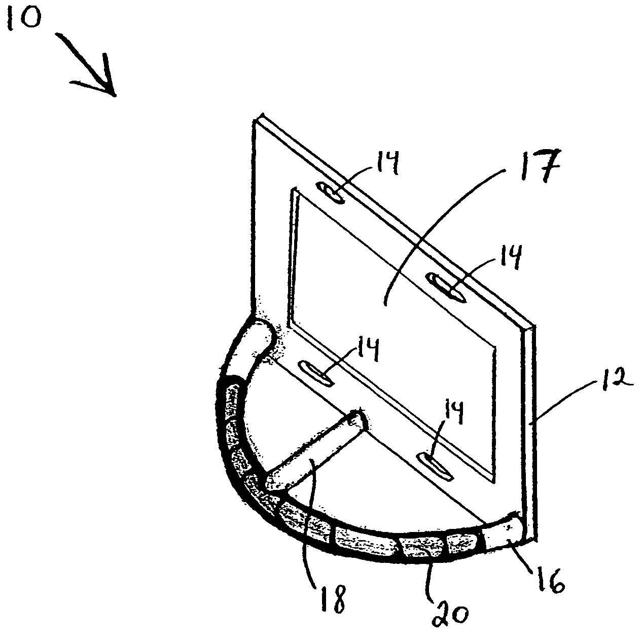
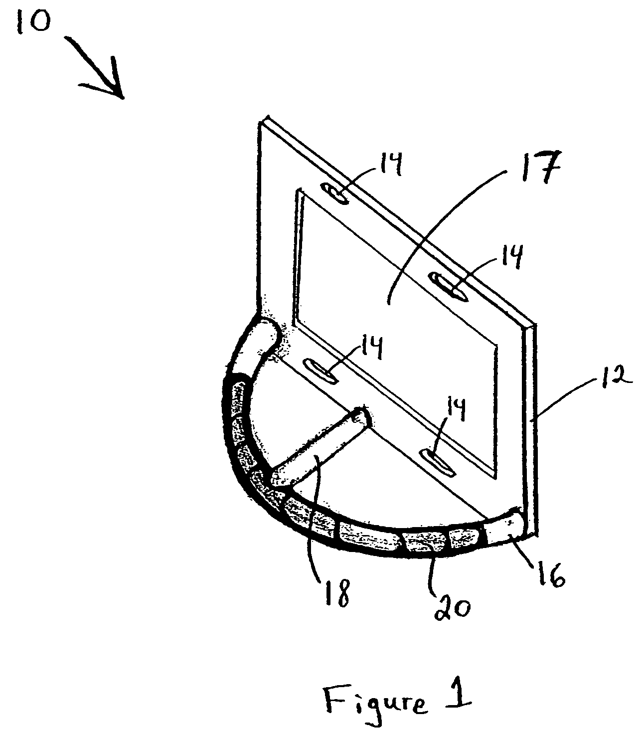
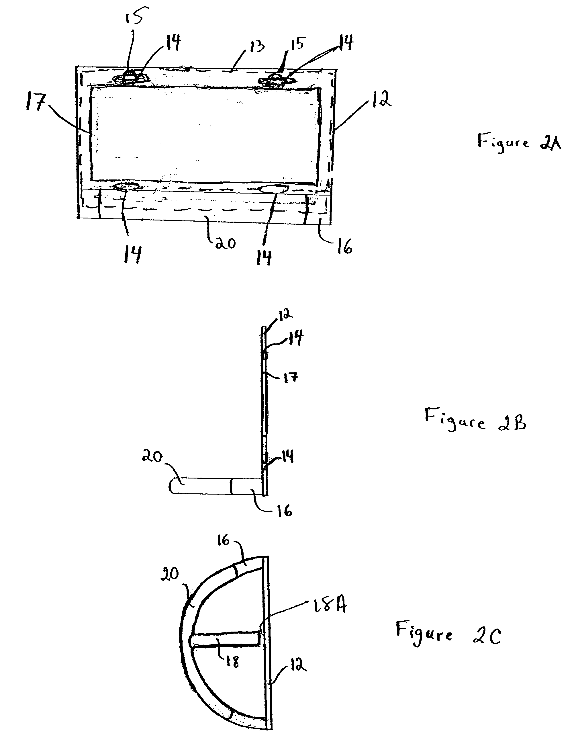
[0027]FIGS. 1 through 2C illustrate a bumper guard 10 having a substantially flat and rectangular base plate 12 having at least one recess 14 therein and preferably having a central opening 17 for making the plate lighter, pliable or able to accommodate slight protrusions from the vehicle. The recesses 14 are disposed at locations on the plate 12 to align with a standard arrangement of recesses 26 (see, FIGS. 3 and 4) provided on a bumper or body 24 of a vehicle for receiving a fastening device in order to mount a license-plate 13 thereto. At least one guard arm 16 preferably extends perpendicularly from the plate 12. Here, the arm 16 extends along one of the long sides of the rectangular plate 12. As shown, the arm 16 is a metal tube having a first and second end, the arm 16 extends from plate 12 along a long side of the rectangular plate 12 with the first and second ends connecting to opposing corners of the respective long side. The guard bar 16 is shown to form an approximately ...


PUM


Abstract

A bumper guard mountable to a vehicle license-plate mounting fixture, the mounting fixture being adapted to receive a license-plate having at least one mounting recess. The bumper guard comprises a first member having a front and rear surface. The rear surface is configured to be disposed adjacent to the mounting fixture. The license plate can be disposed on the front surface of the first member or on the rear surface between the rear surface of the first member and the mounting fixture. At least one recess in the first member is arranged to align with a fastening member of the vehicle license plate mounting fixture. At least one guard arm extends a predetermined distance from the front surface of the first member. The first member is mountable to the vehicle license plate fixture fastening member by at least one fastening device.

Description

BACKGROUND OF THE INVENTION[0001]The present invention relates to automotive protective attachments, and more specifically to a bumper guard attachable at a license-plate mounting area via license-plate mounting fasteners to a vehicle's bumper or body for absorbing low-speed impacts and preventing damage to the bumper and / or body surface.[0002]According to the applicant's knowledge, the current state of the art includes bumper guards which extend in front of and surround the license-plate, but are mounted underneath the bumper, to the bumper support or otherwise to the vehicle undercarriage. Such undercarriage type mountings usually requires drilling holes in the support structure for mounting what is usually a heavy grade steel guard. One such device is illustrated in U.S. Des. Pat. No. 275,475 issued to Turkleson. Other existing bumper guards are custom designed to the shape of a particular vehicle's bumper or body panel. These require substantial work and / or expense to attach or ...

Claims


Application Information

Patent Timeline
Patent Type & Authority Patents(United States)
IPC IPC(8): B60R19/50
CPCB60R13/10B60R19/00
Inventor LEVINE, JEFFREY K
Owner LEVINE JEFFREY K
Why Eureka
Try Eureka