Cable or the like protection and guide device

a protection and guide device technology, applied in the direction of electric cable installation, cable fittings in presence of gas/oil, mechanical apparatus, etc., can solve the problems of large number of parts, displacements between a side plate and a connecting member, and large assembly and maintenance costs, so as to reduce assembly operation and reduce parts. the effect of number of parts and excellent endurance on repeated flexion fatigu

Active Publication Date: 2008-01-08
TSUBAKIMOTO CHAIN CO
View PDF11 Cites 14 Cited by
  • Summary
  • Abstract
  • Description
  • Claims
  • Application Information

AI Technical Summary

Benefits of technology

[0013]Since a number of spaced side plates are connected to each other in a longitudinal direction and connecting arms are bridged over flexion inner circumferential sides and flexion outer circumferential sides of the side plates with predetermined intervals, a cable or the like can be accommodated in a cable accommodating space along the longitudinal direction formed by the side plates and the connecting arms. Additionally, the following peculiar effects can be obtained.
[0014]The front side plate portion is connected to a precedent side plate, a rear side plate portion is connected to a subsequent side plate and a coupling portion is interposed between the front side plate portion and the rear side plate portion. The number of parts is reduced and their assembly operation is reduced.
[0015]And since the coupling portion includes a thin plate-shaped central flexion allowable region and base end continuous regions with gradually increased plate thickness from a central flexion allowable region side toward the front side plate portion and rear side portion respectively, the thin plate-shaped central flexion allowable region realizes smooth repeated flexional movement and the base end continuous regions disperse a stress concentration which is liable to occur during flexed position restriction so that excellent endurance on repeated flexion fatigue and a long life can be exhibited.
[0016]The invention attains the above-mentioned object by providing a side plate having at least one linear position holding surface which holds a linear connection state of the side plate. The invention further provides a side plate having at least one flexed position restricting surface.
[0017]Further, according to the cable or the like protection and guide device of the invention, a linear position holding surface, which holds a linear connection state of said side plate, is formed on a flexion outer circumferential side portion and flexion inner circumferential side portion. A flexed position restricting surface, which restricts the flexed connection state of said side plate, is formed on a flexion outer circumferential side portion and a flexion inner circumferential side portion of said plate, a load which is liable to occur at a coupling portion, which becomes a flexible portion during restriction of a flexed position, is avoided so that excellent endurance can be exhibited. A surface contact load between side plates which is generated during a flexed position restriction and a held linear position is dispersed into two parts of a flexion inner circumferential side and a flexion outer circumferential side of said side plate so that a linear connection state and a flexed connection state can be endurably and reliably held.
[0018]Since a concave / convex engagement mechanism which engages the side plates with each other is provided between a rear side plate portion in a precedent side plate and a front side plate portion of in the side plate, the adjacent side plates are detachable through the concave / convex engagement mechanism so that maintenance during coupling and decoupling can be easily attained.

Problems solved by technology

In Patent Reference 1, since a side plate and a coupling element are separately formed, a large number of parts are required which necessitates considerable assembly and maintenance.
Further, in the energy guide chain as in the Patent Reference 1, since side plates are connected to each other by fitting a different element from the side plates between the side plates, there was a problem that displacements are gradually generated between a side plate and a connecting member by repetition of flexional movements between links.
This causes chain damage when a side plate is disconnected.
Further, in a case where the disconnection between the side plate and the coupling element in such a coupling portion does not occur, there was a problem that an excessive stress concentration is generated at the coupling portion during flexional movement whereby the coupling portion is broken.
In Patent Reference 2 since a connecting rod is formed in a protruding manner outside a side plate, the connecting rod supports a load under certain conditions such that there is a possibility that the connecting rod may break thus shortening the service life of the device.
That is in the protection and guide device of the Patent Reference 2, there was a problem that a flexion portion composed of a connecting rod is broken by a load applied at the time of the restriction of flexion so that a service life of the guide device is shortened.
Further, in the protection and guide device of Patent Reference 2, since the side plates are connected to each other by fitting a connecting rod between the side plates into a connecting groove, there was a problem that displacements are gradually generated between the connecting rod between the side plates and the connecting groove by repetition of flexional movements between link bodies and the guide device is decomposed by disconnection of such a side plate at a coupling portion whereby breakage is liable to occur.
Further, in a case where the disconnection between the connecting rod and the connecting groove in such a coupling portion does not occur, there is a problem that an excessive stress concentration is generated at the base end portion during flexional movement whereby the connecting rod protruded from the side plate is broken.

Method used


Image

  • Cable or the like protection and guide device
  • Cable or the like protection and guide device
  • Cable or the like protection and guide device

Examples


example 1

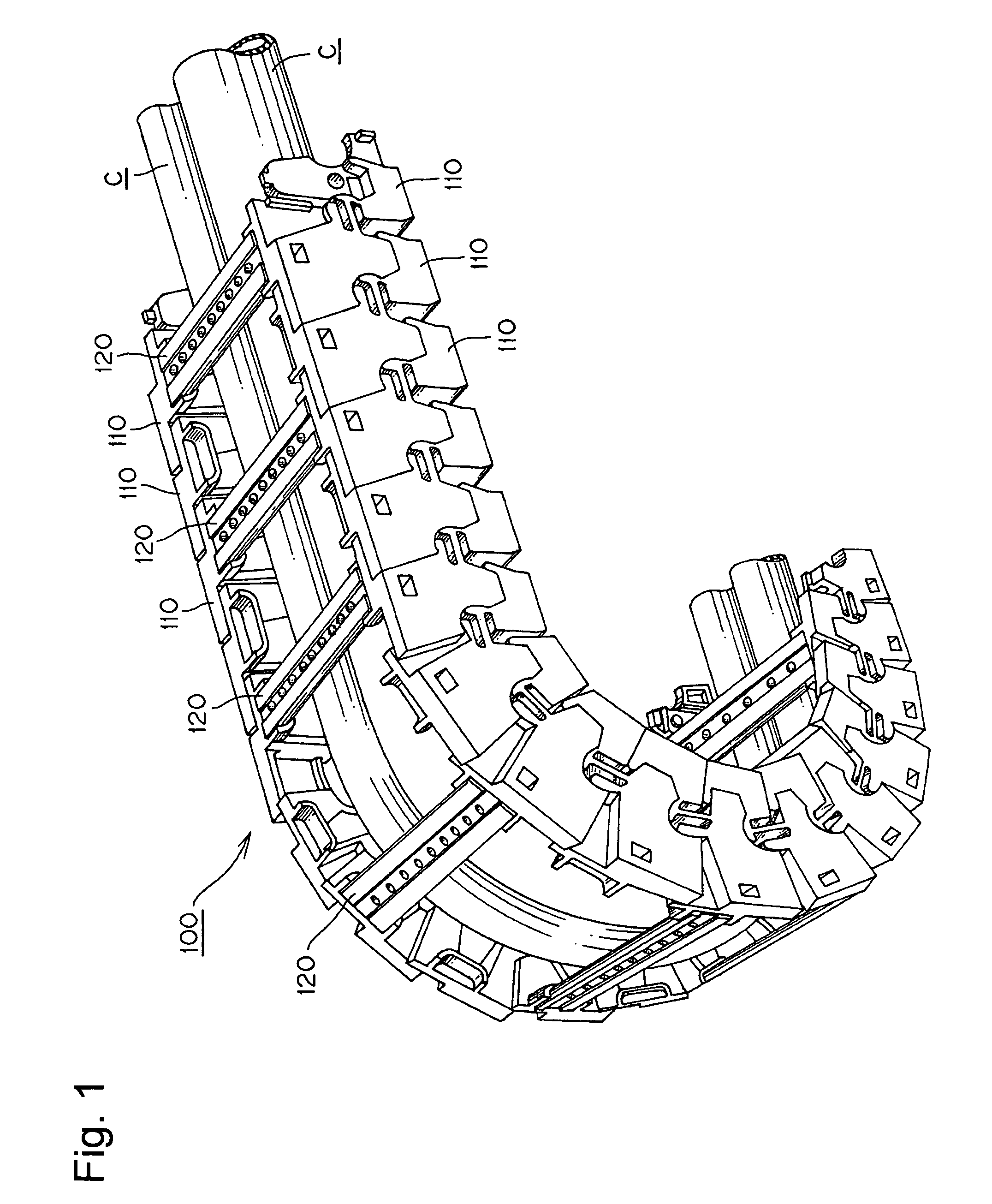
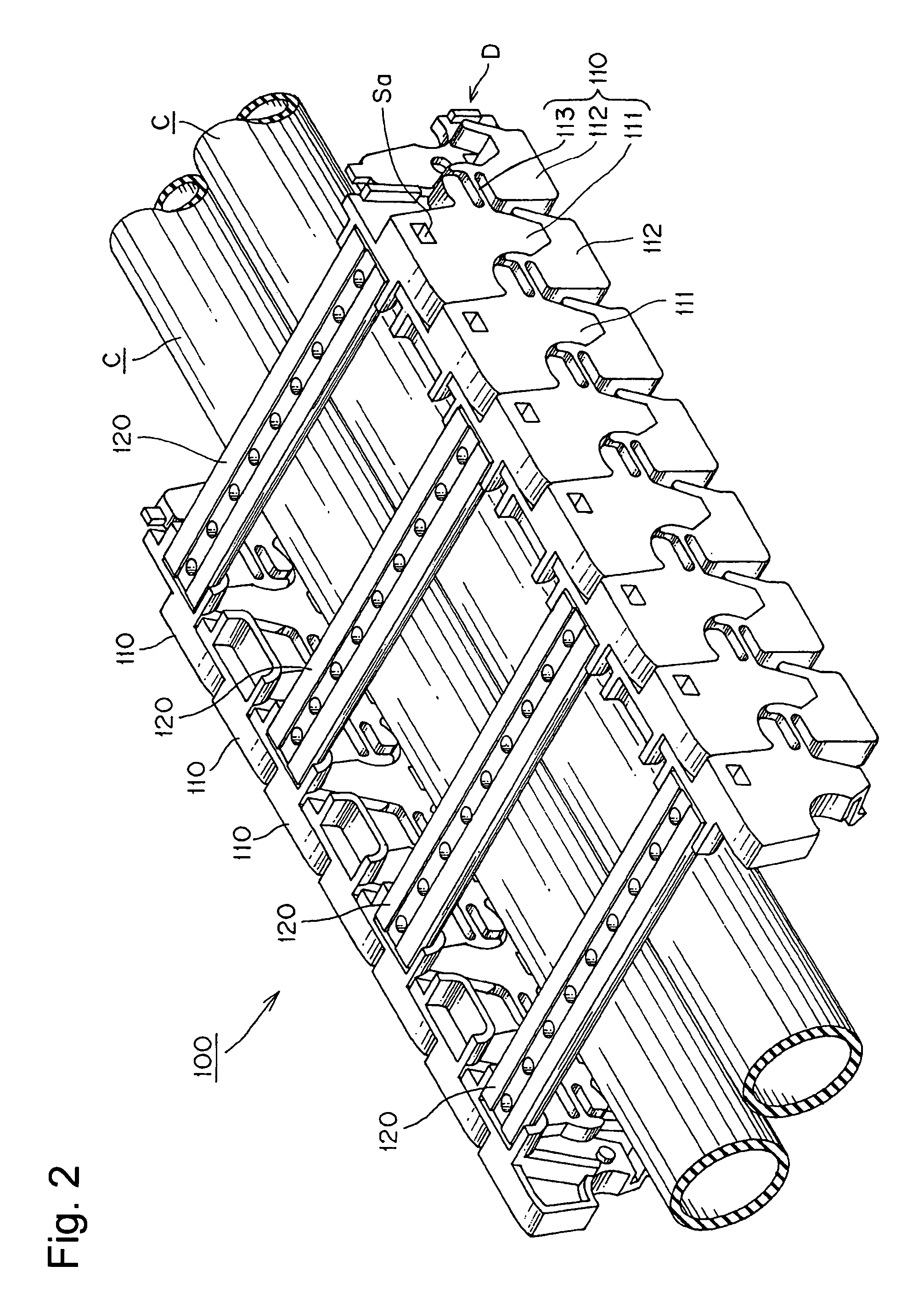
[0038]A cable or the like protection and guide device 100, which is an example of the present invention, will be described with reference to FIGS. 1 to 9 below.

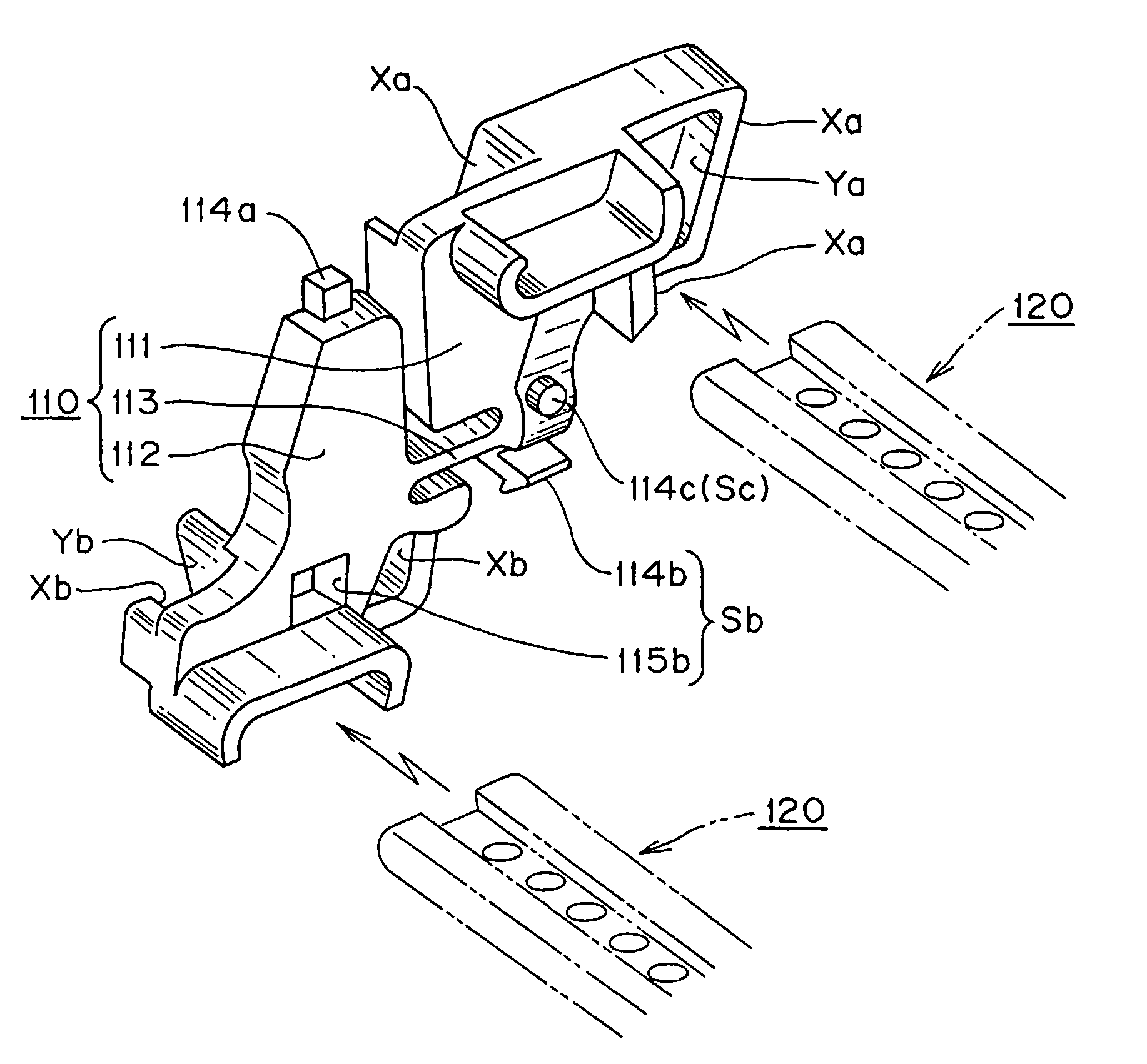
[0039]Here, FIG. 1 is an entire perspective view of a cable or the like protection and guide device 100 which is an example of the present invention. FIG. 2 is a perspective view of a linear connection state in the cable or the like protection and guide device 100 in FIG. 1. FIG. 3 is a perspective view of a flexion connection state in the cable or the like protection and guide device 100 in FIG. 1. FIGS. 4 to 7 are perspective views of a side plate used in the cable or the like protection and guide device 100, particularly, FIG. 4 is a perspective view of a side plate shown by the arrow D in FIG. 2, FIG. 5 is a perspective view of a side plate viewed from the E direction in FIG. 4, FIG. 6 is a perspective view of a side plate viewed from the F direction in FIG. 4, FIG. 7 is a perspective view of a side plate viewed from the ...


PUM


Abstract

A cable or the like protection and guide device is disclosed in which inadvertent disconnection in a coupling portion of a side plate due to the repetition of flexional movements is avoided. Stress concentration is reduced in a flexion portion during restriction of flexional movements whereby excellent endurance on repeated flexion fatigue can be exhibited and in which the number of parts and the assembly operation can be reduced. Plates disposed in a right and left pair are integrally formed by a front side plate portion 111, a rear side plate portion 112, and a flexible coupling portion 113 interposed between the front side plate portion 111 and the rear side plate portion 112. The coupling portion 113 includes a thin plate-shaped central flexion allowable region 113a and base end continuous regions 113b, 113b with gradually increased plate thickness from the central flexion allowable region 113a side toward the front side plate portion 111 and rear side portion 112, respectively.

Description

[0001]This patent application claims priority to Japanese Patent Application No. 2005-285262 filed Sep. 29, 2005.TECHNICAL FIELD[0002]The present invention relates to a cable or the like protection and guide device. More specifically the invention relates to a cable or the like protection and guide device suitable for accommodating a cable or the like which supplies a movable member of an industrial machine with electric power or energy of compressed air.BACKGROUND TECHNOLOGY[0003]A conventional cable or the like protection and guide device such as an energy guide chain connects side plates to each other with a separate coupling element from the side plate is known and illustrated in Patent Reference 1.[0004]Another conventional cable or the like protection and guide device connects side plates to each other by fitting a connecting rod integrally formed on each side plate to a connecting groove between side plates is also known and disclosed in Patent Reference 2.[0005]Patent Refere...

Claims


Application Information

Patent Timeline
Patent Type & Authority Patents(United States)
IPC IPC(8): F16G13/00
CPCF16G13/16H02G11/006
Inventor UTAKI, AKIHIKO
Owner TSUBAKIMOTO CHAIN CO
Why Eureka
Try Eureka