Remote monitoring system for exterminating pest and a method thereof

a technology of remote monitoring and pest control, applied in the direction of digital computer details, instruments, audio advertising, etc., can solve the problems of destroying buildings and facilities, bringing huge losses, and destroying houses or buildings, and achieve the effect of effective pest control

Active Publication Date: 2008-01-08
CHUNWOO ENVIRONMENT SERVICE
View PDF12 Cites 51 Cited by
  • Summary
  • Abstract
  • Description
  • Claims
  • Application Information

AI Technical Summary

Benefits of technology

[0008]Yet another objective of the present invention is to provide a remote monitoring method for exterminating pest by collecting and managing the information on pest ecology according to zones, thereby effectively performing pest control on the pest control subject sites.

Problems solved by technology

Pest brings tremendous losses, by invading houses or buildings and damaging to buildings and facilities, giving unpleasant feelings to residents, and carrying germs and pathogenic organisms.
A problem with the conventional method is that it is difficult to obtain detailed information with respect to the ecology of the pest inside the pest control subject site, such as invasion paths of the pest, location of activity, types, chemicals to which the pest have tolerance, unless the service technician personally visits and closely investigates the site.
In case a pest control measure is established by obtaining information through site visits, a large cost of human resources and extra expenses are incurred.
These conventional systems and methods, however, lack means for effectively performing pest control.
Especially, these conventional systems and methods do not consider characteristics of zones or sections in a building even though the appearance and activity of the pest may be different from zone to zone in the same pest control subject site, according to the circumstances of each site.
Accordingly, even if information required to perform pest control is obtained, the efficiency of the pest control may not be optimized since the obtained information is not systematically managed for each zone in a building.
Otherwise, he has to apply the pest control measure to the whole pest control subject site even when only some zones or sections in that building are invaded by the pest despite of inefficiency and excessive use of chemicals.

Method used


Image

  • Remote monitoring system for exterminating pest and a method thereof
  • Remote monitoring system for exterminating pest and a method thereof
  • Remote monitoring system for exterminating pest and a method thereof

Examples


first embodiment

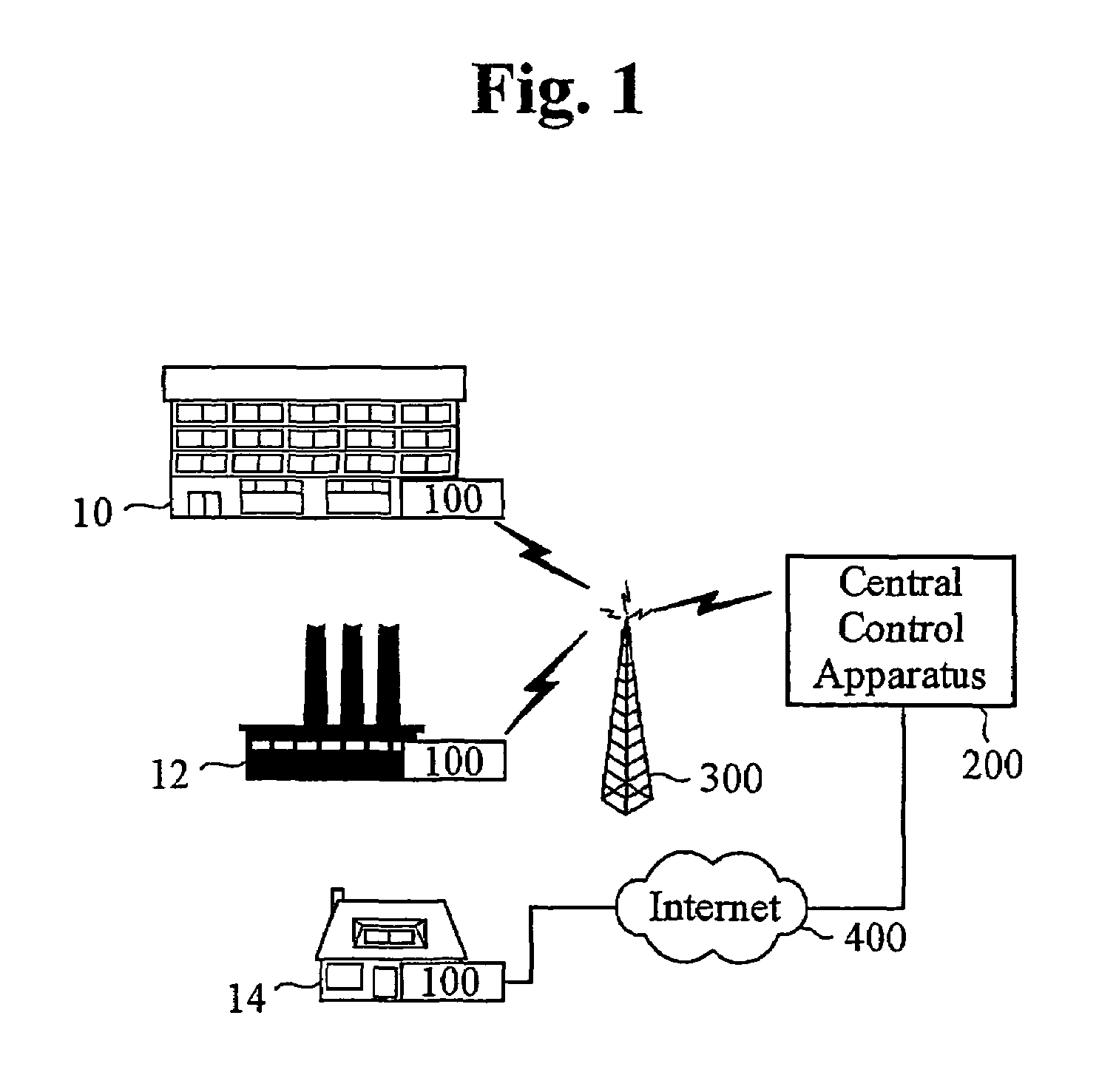
[0036]Referring to FIG. 1, a schematic diagram shows a remote monitoring system for exterminating pest in accordance with the present invention.

[0037]As illustrated, the remote monitoring system in accordance with the first embodiment of the present invention comprises remote monitoring apparatus 100 and central control apparatus 200. Remote monitoring apparatus 100 is installed at each building 10, 12, 14, i.e., the pest control subject site, and monitors the activities of pest, collects information related to the activities, and transmits the collected information through wireless communication network 300 or wired communication network 400, such as the Internet or a public switched telephone network. Central control apparatus 200 receives the information related to pest transmitted from remote monitoring apparatus 100, analyzes the received information, and manages the analyzed information. Herein, the term “subject site” means a building at which pest appear or may appear, or pr...

second embodiment

[0107]FIG. 12 is a schematic diagram conceptually showing a remote monitoring system for exterminating pest in accordance with the present invention. For ease of reference, components identical to those shown in FIG. 1 have the same reference numerals.

[0108]A difference between the first and second embodiments of the present invention is that central control apparatus 200 re-transmits the analysis result of the pest-related information to a user of each building 10, 12, and 14 and / or the service technician. Specifically, the service technician receives the analysis result of the pest-related information using mobile communication terminal 70, such as a personal digital assistant (DA) or a mobile phone, and performs pest control operation suitable for each site 10, 12, and 14.

[0109]FIG. 13 is a schematic diagram conceptually showing central control apparatus 200 in accordance with the second embodiment of the present invention.

[0110]In the second embodiment, central control apparatus...

third embodiment

[0114]FIG. 14 shows a schematic diagram a remote monitoring system for exterminating pest in accordance with the present invention. For ease of reference, components identical to those shown in FIG. 1 have the same reference numerals.

[0115]A difference between the second and third embodiments of the present invention is that pest-related information may be directly transmitted from remote monitoring apparatus 100 to mobile communication terminal 70 in the third embodiment. Although mobile communication terminal 70 shown in FIG. 14 communicates with remote monitoring apparatus 100 by wireless communication, mobile communication terminal 70 can also be configured to communicate with remote monitoring apparatus 100 by both wired and wireless communication. In the third embodiment of the present invention, the service technician may receive an instruction to move to a pest control subject site from remote monitoring apparatus 100 installed at that site or central control apparatus 200. ...


PUM


Abstract

A remote monitoring system for exterminating pest comprises at least one sensor, installedd at a plurality of zones of a subject site, for sensing movement of the pest in the zones, and producing and transmitting detection signals corresponding to the movement; at least one remote controller installed at the subject site, for receiving the detection signals and processing and transmitting the received detection signals; and a central control apparatus for receiving information from at least one remote controller, analyzing the information and managing the analyzed information by the zones.

Description

TECHNICAL FIELD[0001]The present invention relates to a remote monitoring system for exterminating pest and a method thereof, and more particularly to a remote monitoring system for exterminating or preventing pest by detecting and monitoring their invasion and activity in a remote place.BACKGROUND ART[0002]Pest brings tremendous losses, by invading houses or buildings and damaging to buildings and facilities, giving unpleasant feelings to residents, and carrying germs and pathogenic organisms. Accordingly, various methods for exterminating and preventing pest and their invasion have been proposed. Herein, the term “pest” represents all harmful insects and animals, such as cockroaches, ants, rats and weasels, and harmful birds.[0003]In a conventional pest control method, a pest control service technician (hereinafter, “service technician”) visits a building (hereinafter, “pest control subject site”) and understands the situation by personally investigating the circumstances and inte...

Claims


Application Information

Patent Timeline
Patent Type & Authority Patents(United States)
IPC IPC(8): G08B23/00A01M1/00A01M1/20G08B1/08G09F25/00G08C17/02A01M1/02A01M31/00
CPCA01M31/002A01M1/026
Inventor CHYUN, CHAN HYUK
Owner CHUNWOO ENVIRONMENT SERVICE
Why Eureka
Try Eureka