System and method for distributed multicast routing

a distributed multicast and routing technology, applied in the field of packet switching communication networks, can solve the problem of rendering such a distributed unicast forwarding scheme unsuitable for routing multicast packets

Inactive Publication Date: 2008-01-08
HEWLETT-PACKARD ENTERPRISE DEV LP
View PDF14 Cites 51 Cited by
  • Summary
  • Abstract
  • Description
  • Claims
  • Application Information

AI Technical Summary

Problems solved by technology

However, the necessary change in the destination MAC address renders such a distributed unicast forwarding scheme unsuitable for routing multicast packets, for which the MAC address should not change within the switching fabric.

Method used


Image

  • System and method for distributed multicast routing
  • System and method for distributed multicast routing
  • System and method for distributed multicast routing

Examples


Embodiment Construction

Synopsis

[0020]The following description begins with a discussion of bridging, fabrics and distributed operation, explains the context of distributed routing and proceeds to an explanation of distributed multicast routing according to the invention.

Context

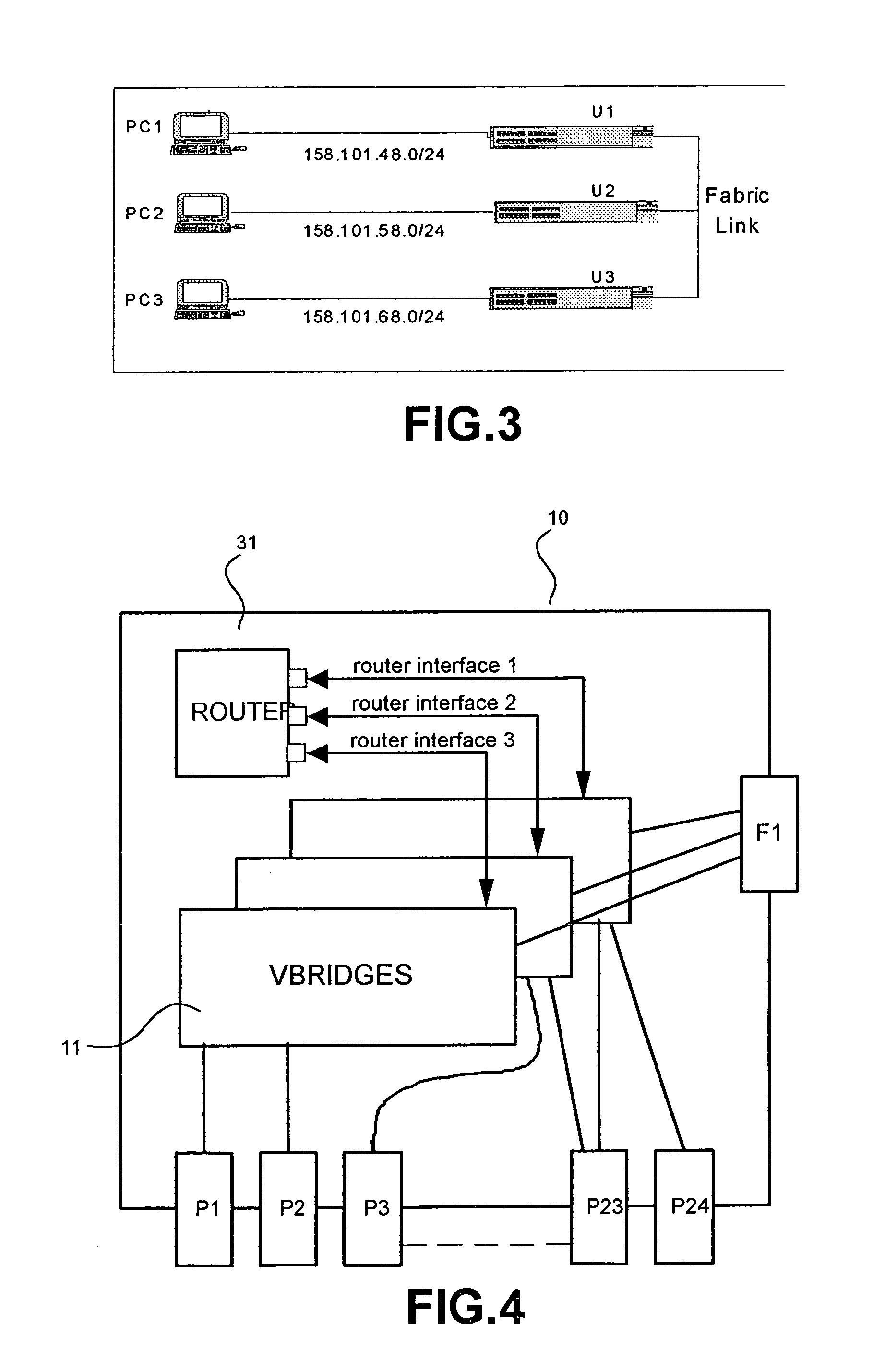
[0021]It is generally presumed in the description that follows that the system for the conveyance of packets which have, among other things, media access control (MAC) addresses and IP (network) addresses corresponding to the second or data link layer and third or logical link layer of the OSI Network Model. It also presumed that the physical network has a multiplicity of ‘layer 2’ domains or sub-nets; for this purpose it may be notionally partitioned into virtual local area networks (VLANs).

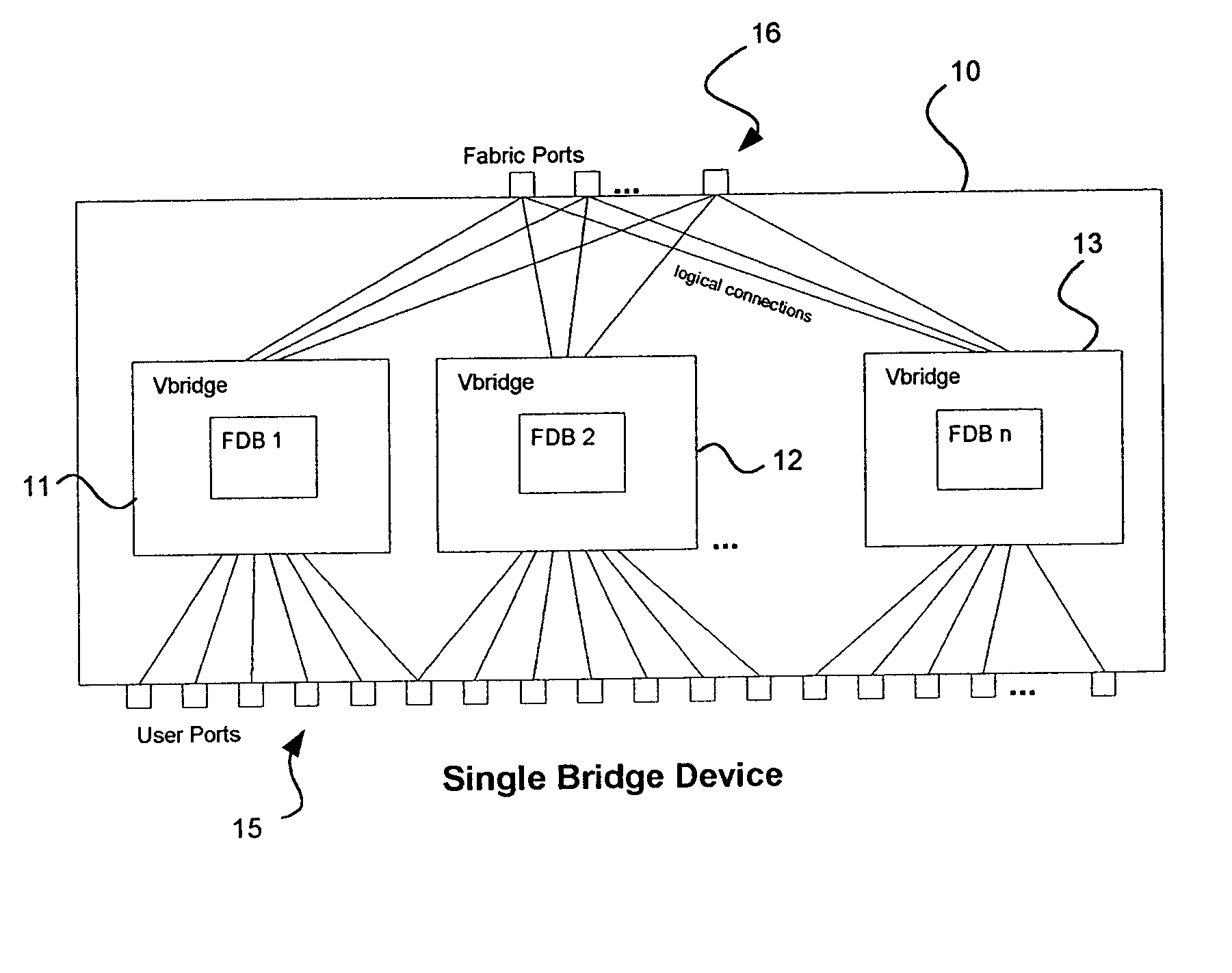
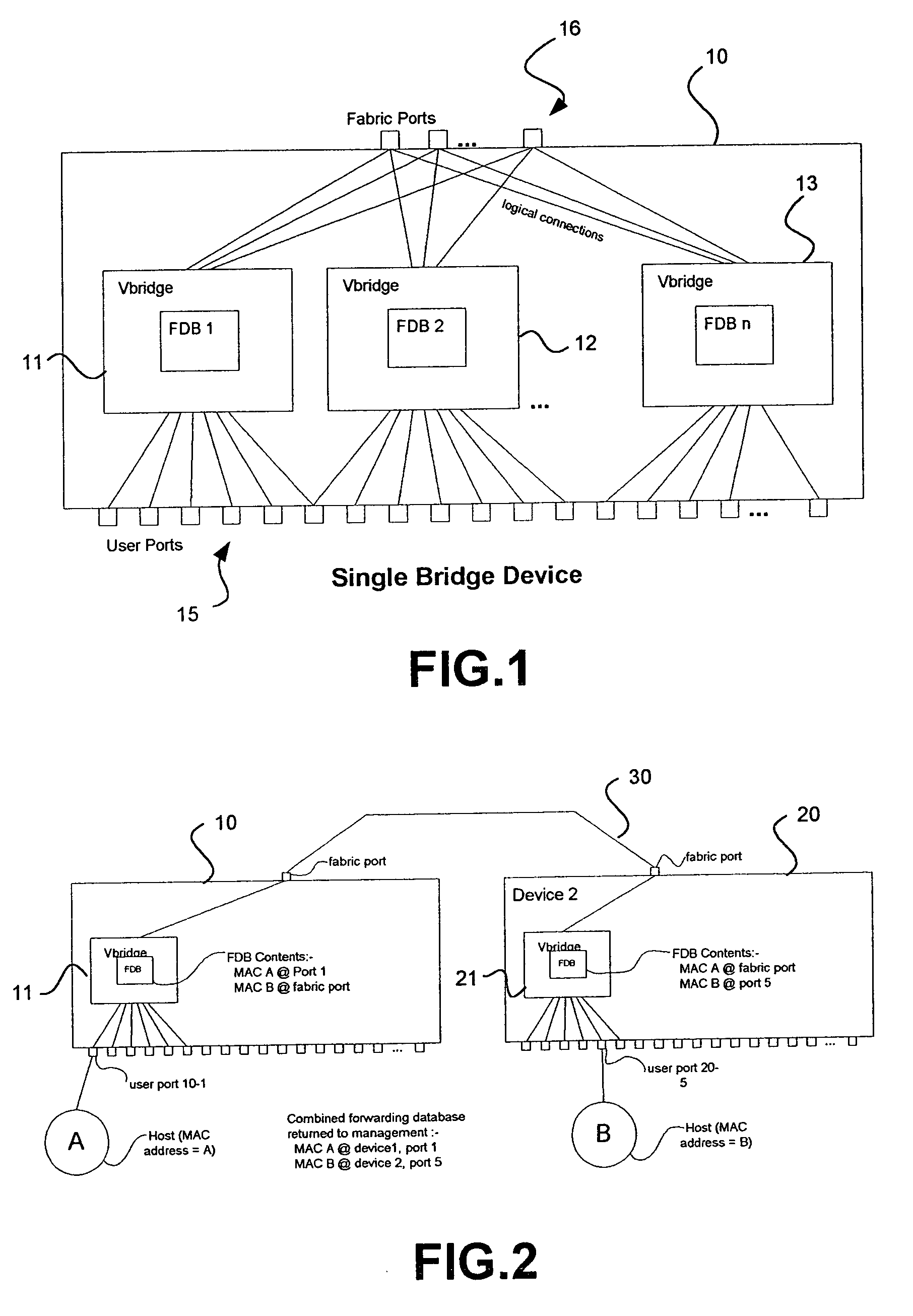
[0022]When several individual data switching units are connected to form a fabric, their functionalities may be distributed among the individual units in the fabric. It is generally important to allow this distribution to occur so that the entir...


PUM


Abstract

A distributed router composed of individual units connected by links in a routing fabric which appears to be a single network entity routes multicast packets by bridging to the final unit in the fabric. At the final unit the packet is replicated as necessary and routed. The scheme avoids multiple transmission of the same packet across the fabric.

Description

FIELD OF THE INVENTION[0001]This invention relates to packet-switched communication networks, particularly though not exclusively those employing media access control (MAC) addressing and network (IP) addressing of packets. More particularly the invention relates to a fabric of units organised as a single virtual multicast router and units intended for or capable of use in such a fabric.BACKGROUND OF THE INVENTION[0002]It is known, particularly for network switches, to interconnect a multiplicity of network units into a switching ‘fabric’ so that in effect, and particularly in relation to the external network, the units act as a single network entity. One of the purposes of a fabric of network units is the provision of ‘resiliency’ that is to say the ability of the switching fabric to continue operation, so far as is feasible, notwithstanding a fault in or removal of one of the units of the fabric or one of the links connecting the units of the fabric. Early forms of such a fabric w...

Claims


Application Information

Patent Timeline
Patent Type & Authority Patents(United States)
IPC IPC(8): H04L12/06H04L12/18H04L12/56
CPCH04L45/04H04L45/16H04L45/44H04L12/56H04L45/00
Inventor AQUINO, FRANCISCOGOODFELLOW, MAURICE A.WEYMAN, RAPHAEL J.
Owner HEWLETT-PACKARD ENTERPRISE DEV LP
Why Eureka
Try Eureka