

Paint ball gun having paint ball dispenser with threaded connector
a paint ball gun and connector technology, applied in the field of paint ball guns, can solve the problems of inconvenient use, inconvenient disassembly of the paint ball dispenser, and insufficient locking force of the gun, and achieve the effect of sufficient locking for
- Summary
- Abstract
- Description
- Claims
- Application Information
AI Technical Summary
Benefits of technology
Problems solved by technology
Method used
Image

Examples
Embodiment Construction
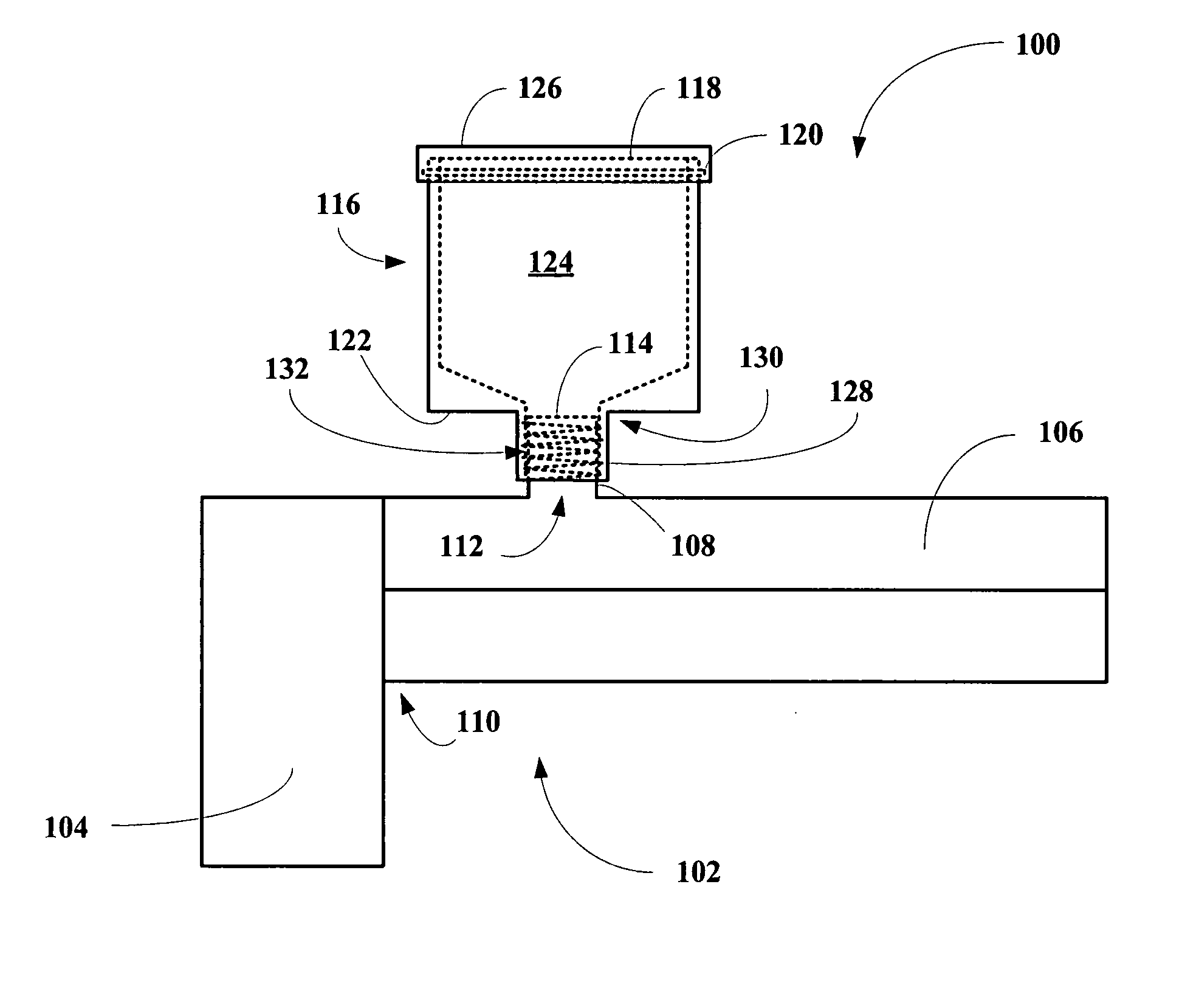
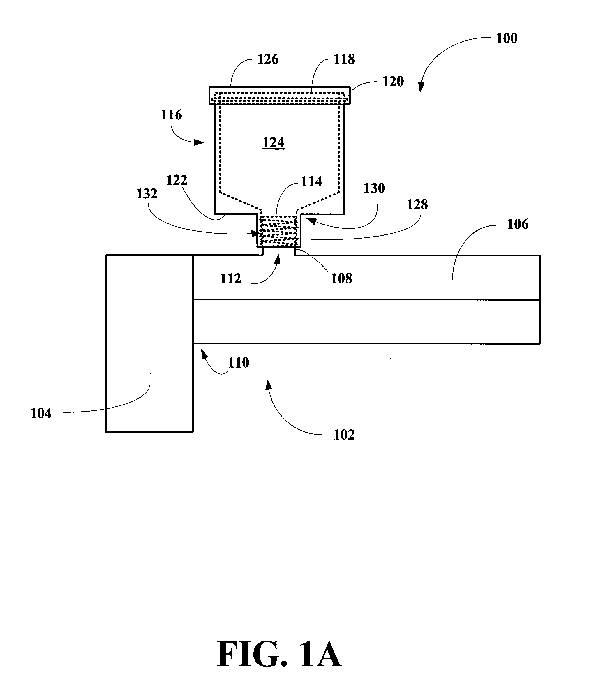
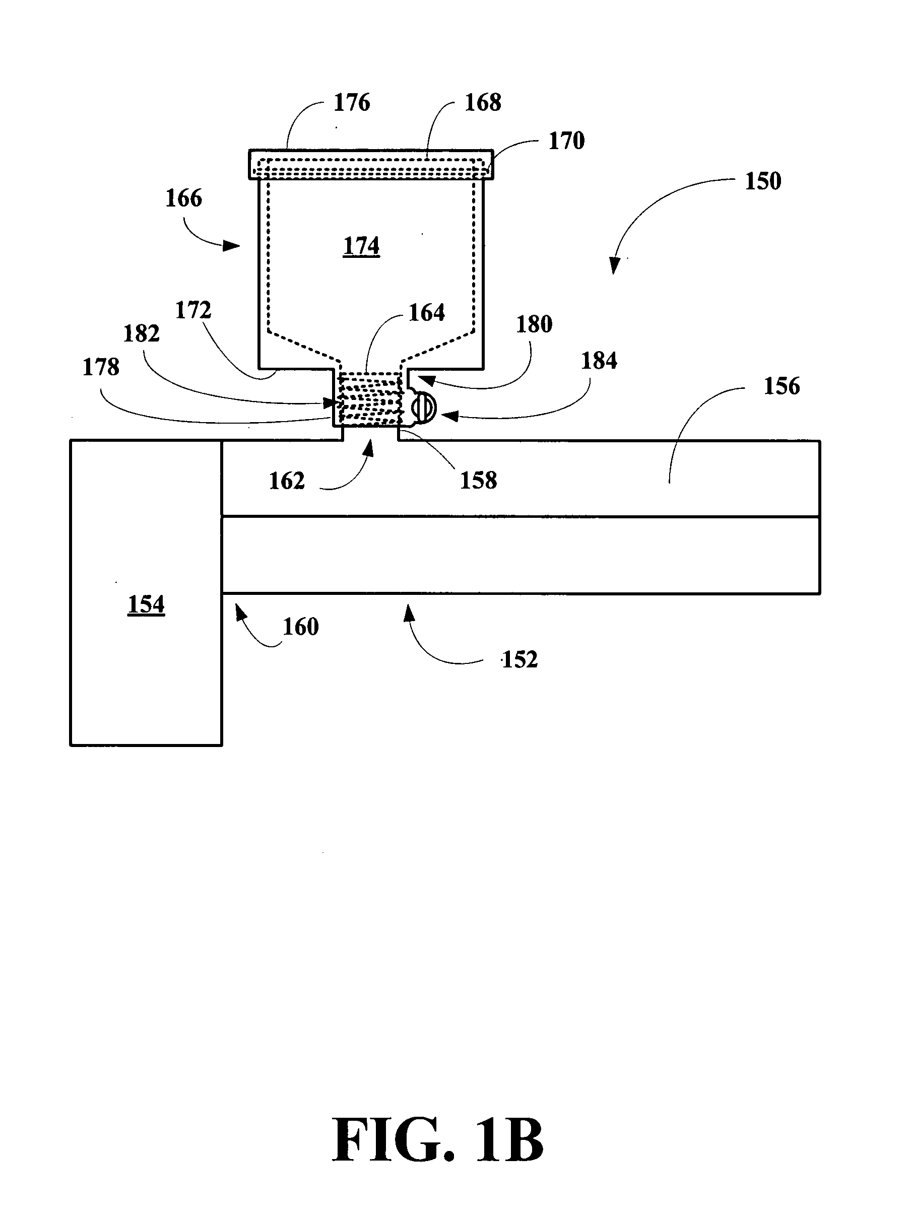
[0027]The inventor has found that a paint ball dispenser can be constructed that reduces or minimizes the dispenser from unloosening and / or falling off of the paint ball gun during paint ball activities, which significantly interferes with user participation in the paint ball activities. The inventor has found that the reduction can be achieved by adding an interlocking connection such as a threaded connection between the paint ball dispensing neck of the dispenser and either the feed tube of the barrel of a paint gun or between the paint ball dispensing neck of the dispenser and a hollow connecting member interposed between the dispenser and the feed tube of the gun. The preferred assembly of this invention includes a connecting member interposed between the dispenser and the gun, where the assembly includes an interlocking connection between the dispenser and the connecting member and where the connecting member acts as a paint ball conduit between the dispenser and the feed tube ...
PUM
 Abstract
Description
Claims
Application Information