A fast electric locking device

A locking device, electric technology, applied in the direction of fixing devices, mechanical equipment, etc., can solve problems such as inability to unlock, difficulty in unlocking, high friction, etc., to achieve the effect of avoiding inability to move and good anti-locking performance

Active Publication Date: 2015-09-02
CHINA ELECTRONIC TECH GRP CORP NO 38 RES INST
View PDF7 Cites 2 Cited by
  • Summary
  • Abstract
  • Description
  • Claims
  • Application Information

AI Technical Summary

Problems solved by technology

When the motion mechanism cannot be fully matched, the pin is compressed and deformed, resulting in a large friction force, especially when the friction force is large, it is difficult to unlock, or even impossible to unlock

Method used


Image

  • A fast electric locking device
  • A fast electric locking device
  • A fast electric locking device

Examples


Embodiment Construction

[0026] The present invention will be further described through the embodiments below in conjunction with the accompanying drawings.

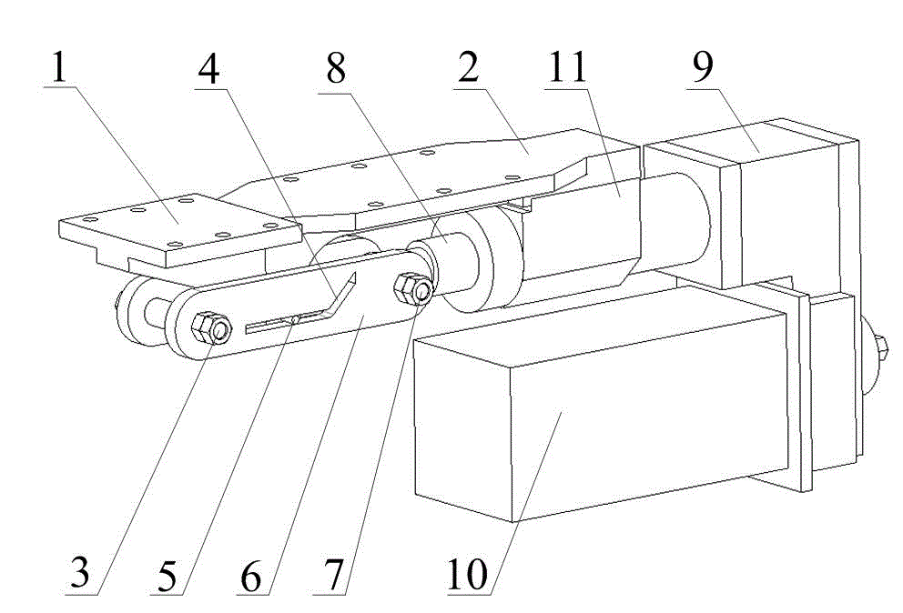
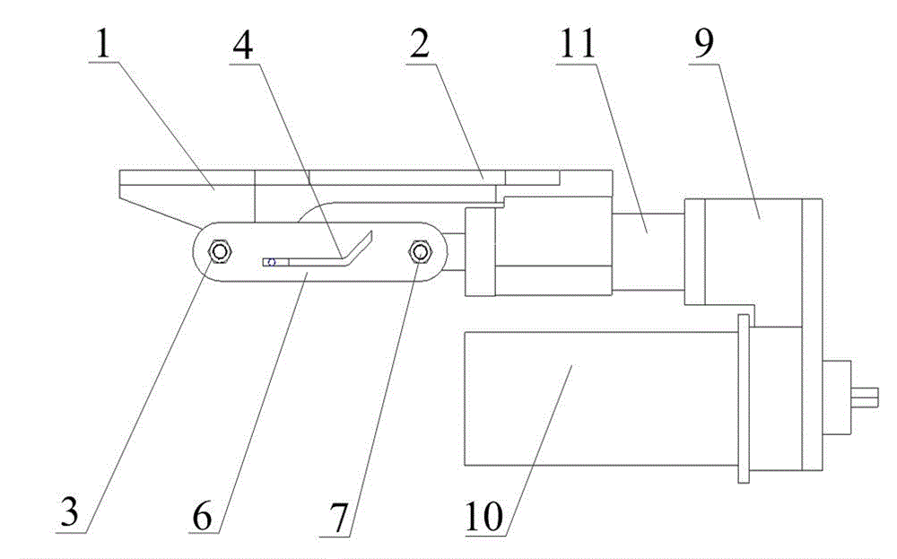
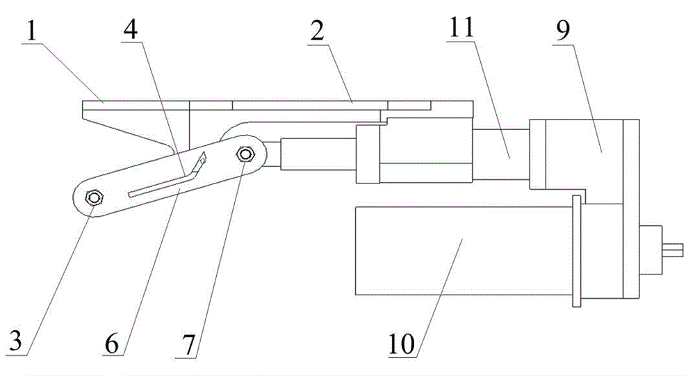
[0027] see figure 1 , Figure 4 , a fast electric locking device, including a motor 10, a reducer 9, a screw support 11, a screw shaft 12, a sliding shaft 8, a screw nut 13, a fixed locking support 1, and a transmission locking support 2 , swing rod 6, connecting shaft 7, sliding bolt 5 and locking shaft 3; screw support 11 is a horizontal shell, and a long hole is provided in the shell, and one end of the shell is provided with a vertical connecting surface, and the front section of the shell The upper part is provided with a horizontal connecting surface; the sliding shaft 8 is a long tube shaft, and its end is provided with a pin hole. The tail of the long tube shaft of the sliding shaft 8 is fixedly connected with the screw nut 13; the screw shaft 12 is a two-section rod shaft with a long section and a short section, the long section is th...


PUM


Abstract

The invention relates to a fast electric locking device. The fast electric locking device comprises a motor, a speed reducer, a lead screw support, a lead screw shaft, a sliding shaft, a fixed locking support, a transmission locking support, an oscillating bar, a connecting shaft, a sliding bolt and a locking shaft, wherein the speed reducer is connected with the motor and located above the motor, a transmission shaft of the lead screw shaft is in key connection with a gear and is arranged at the output end of the speed reducer through a bearing, torque is transmitted between the motor and the speed reducer through gear meshing between the shafts, the motor drives the lead screw shaft through the speed reducer so that the sliding shaft can be moved by the lead screw shaft, and a locking state and an unlocking state can be formed by the fixed locking support relative to the transmission locking support under the action of the oscillating bar. According to the fast electric locking device, controllability of locking and unlocking can be achieved, a better dead locking preventing performance is achieved, and manual unlocking can be achieved through a nut of the locking shaft. The fast electric locking device is stable and reliable in performance and long in service life.

Description

technical field [0001] The invention relates to a mechanical locking device, in particular to an electric locking device. Background technique [0002] In a mechanical motion system, after the motion mechanism reaches a predetermined position, if it is necessary to keep the motion mechanism still for a certain period of time to prevent misoperation, the motion mechanism must be locked. At present, the commonly used locking device mainly adopts the bolt mode to lock the moving mechanism. When the motion mechanism cannot be fully matched, the bolt is compressed and deformed, resulting in a relatively large frictional force, especially when the frictional force is very large, it is difficult to unlock, or even impossible to unlock. Contents of the invention [0003] Aiming at the above-mentioned deficiencies in the prior art, the present invention provides a fast electric locking device. [0004] The purpose of the present invention is achieved through the following technic...

Claims


Application Information

Patent Timeline
Patent Type & Authority Patents(China)
IPC IPC(8): F16B1/00
Inventor 孟国军王磊胡志伟
Owner CHINA ELECTRONIC TECH GRP CORP NO 38 RES INST
Why Eureka
Try Eureka