Rotary button lock

A rotary, push-button technology, applied in the field of aircraft flap locks, can solve the problems of inability to meet the use requirements of military products, large operating space and opening size, and unchanged operation, and achieve fast, reliable, and good aerodynamic unlocking and locking operations. Appearance and easy installation

Pending Publication Date: 2020-11-17
东方蓝天钛金科技有限公司
View PDF0 Cites 1 Cited by
  • Summary
  • Abstract
  • Description
  • Claims
  • Application Information

AI Technical Summary

Problems solved by technology

The rotary quick release lock is easy to use and small in size, but its load bearing capacity is relatively weak; the snap button quick release lock can withstand large loads, but the operating space and opening size are large; the hook tongue quick release lock has good sealing performance And larger load-bearing capacity, but only suitable for larger wall th...

Method used


Image

  • Rotary button lock
  • Rotary button lock
  • Rotary button lock

Examples


Embodiment 1

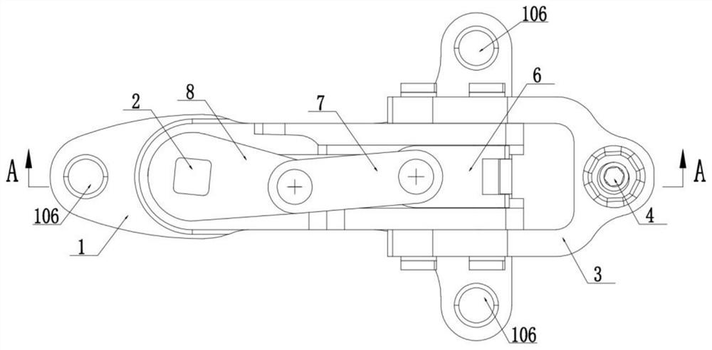
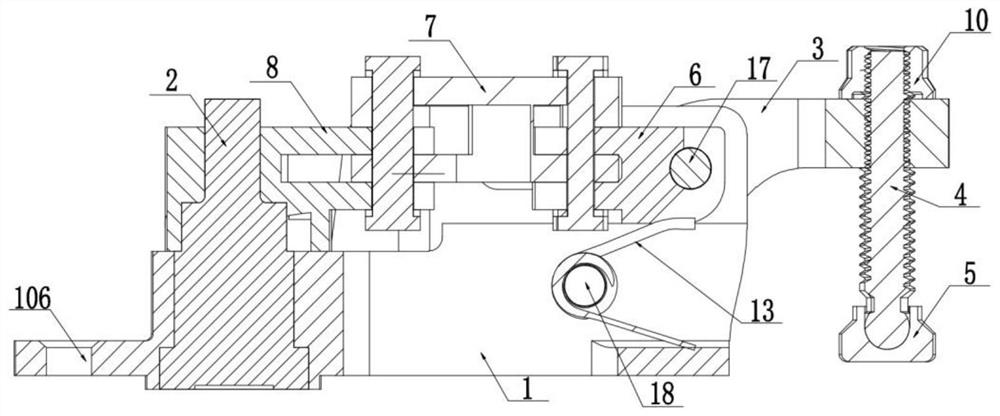
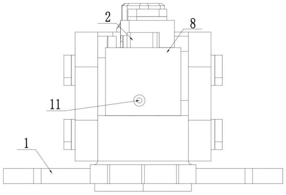
[0057] Example 1, such as Figure 1-Figure 7 As shown, a rotary button lock includes a lock base 1, a driver 2 disposed on the lock base 1, a swing arm 8, a slider 6, a support 3 and a pressure head, and one side of the lock base is provided with a drive The other side of the socket 101 is provided with a chute 102, the driver is set in the drive socket, the slider is installed in the chute, one end of the swing arm is connected to the driver, The other end is hinged with one end of the slider through the connecting rod 7, the support 3 is bent, one end of the support is hinged with the lock seat, the middle part is provided with a guide groove 301, and the other end is connected with the lock seat. The pressure head is connected, and the other end of the slider is provided with a pin 17, and the end of the pin extends into the guide groove.

[0058] The lock seat is provided with a long through hole 107 for the movement of the pin, and the pin passes through the long through...

Embodiment 2

[0067] Example 2, such as Figure 8-Figure 11 As shown, on the basis of Embodiment 1, the driving member 2 includes a shaft housing 201 and a push rod 202 inserted in the shaft housing, the shaft housing is sleeved in the driving socket, and the shaft A through groove 203 is provided on the shell, and a limit block 15 is arranged on the push rod, and the limit block extends into the through groove, and a return spring is arranged on the push rod below the limit block 12. The swing arm is connected to the axle housing. The return spring is sleeved on the push rod between the head of the push rod and the limit block. The function of the return spring is that when the wrench needs to be matched with the slot on the shaft shell, the compressed return spring will push up the push rod so that the shaft shell exposes the slot matched with the wrench. If the wrench is an outer hexagon, the slot will The hole is an inner hexagonal hole. After the wrench is adjusted, the return spring...

Embodiment 3

[0068] Example 3, such as Figure 12-Figure 26 As shown, on the basis of Embodiment 2, a locking mechanism is also included, and the locking mechanism includes a locking ball 9 and a locking spring 19. The locking groove 204 is used, the lock seat is provided with a locking positioning hole 103, and the locking ball and locking spring are installed in the locking positioning hole. When the driving part is an integral part, the locking groove is on the outer surface of the driving part; when the driving part includes a shaft housing and a push rod, the locking groove is on the outer surface of the shaft housing. The locking ball is stuck in the locking groove under the action of the locking spring, which can realize the complete locking of the button lock, and the locking of the button lock is more stable. When unlocking, when the rotational force reaches a certain value, the driving part can be unlocked from the locking ball and rotate with the swing arm, thereby improving th...


PUM


Abstract

The invention discloses a rotary button lock. The rotary button lock comprises a lock bracket, a driving piece, a swing arm, a sliding block, a support and a pressing head, wherein the driving piece,the swing arm, the sliding block, the support and the pressing head are arranged on the lock bracket, a driving insertion hole is formed in one side of the lock bracket, a sliding groove is formed inthe other side of the lock bracket, the driving piece is sleeved with the driving insertion hole, the sliding block is installed in the sliding groove, one end of the swing arm is connected with the driving piece, the other one end of the swing arm is connected with one end of the sliding block, the support is in a bent shape, one end of the support is hinged to the lock bracket, guide grooves areformed in the middle of the support, the other end of the support is connected with the pressing head, a shifting pin is arranged at the other end of the sliding block, the end part of the shifting pin extends into the guide groove, the driving piece comprises a shaft shell and an ejector rod, the shaft shell is sleeved with the driving insertion hole, a through groove is formed in the shaft shell, and a limiting clamping block is arranged on the ejector rod. The rotary button lock is simple in structure, small in size, light in weight, convenient to install and rapid and reliable in unlocking and locking operation, no protruding structure exists on the surface of a covering cap after installation, and the better aerodynamic configuration of an aircraft is guaranteed.

Description

technical field [0001] The invention relates to a rotary button lock, which belongs to the technical field of aircraft flap locks. Background technique [0002] In order to ensure that the airborne equipment on the aircraft is maintained and repaired in a timely manner, the surface of the aircraft needs to be provided with a large number of covers. The covers are divided into quick-release covers and non-quick-release covers according to their characteristics. The lid generally only needs to be simply pressed, twisted, or the entire flap can be opened or closed with a simple tool. [0003] At present, the fast opening and closing of various types of flaps used on aircraft can be mainly divided into several types such as rotary type, screw type, snap button type, hook tongue type, and integral detachable type in terms of mechanism principle and operation mode. Rotary quick-release locks are easy to use and small in size, but relatively weak in load bearing capacity; snap-on ...

Claims


Application Information

Patent Timeline
IPC IPC(8): E05B17/22E05B15/00E05B15/04
CPCE05B15/00E05B15/04E05B17/22E05B2015/0406
Inventor 王肇宇王晓伟牛光景王善岭舒培王晓亮邓兴智
Owner 东方蓝天钛金科技有限公司
Why Eureka
Try Eureka