A fast locking device for guardrail wire rope

A technology of locking device and steel cable, which is applied in the direction of fences, building structures, stepped structures, etc., can solve the problems of insufficient environmental applicability, insufficient locking force, and low work efficiency, and achieve a wide range of installation applications, locks Sufficient tightening force and high working efficiency

Inactive Publication Date: 2017-09-05
MODERN CO LTD
View PDF1 Cites 2 Cited by
  • Summary
  • Abstract
  • Description
  • Claims
  • Application Information

AI Technical Summary

Problems solved by technology

The patent number is: US7198253, the U.S. patent that the title is called: WIRE ROPE CONNECTORS AND TENSIONERS FOR DECK RAILING SYSTEMS discloses a kind of guardrail cable tensioning device, and this guardrail steel cable tensioning device has the following disadvantages: 1. Locking force Not enough, it is easy to loosen under a little external force, and the maintenance cost is high; 2. The installation time is long, the labor cost is high, and the work efficiency is low; 3. The installation angle is only 0 to 45 degrees, and the environmental applicability is insufficient.

Method used


Image

  • A fast locking device for guardrail wire rope
  • A fast locking device for guardrail wire rope
  • A fast locking device for guardrail wire rope

Examples


Embodiment approach 1

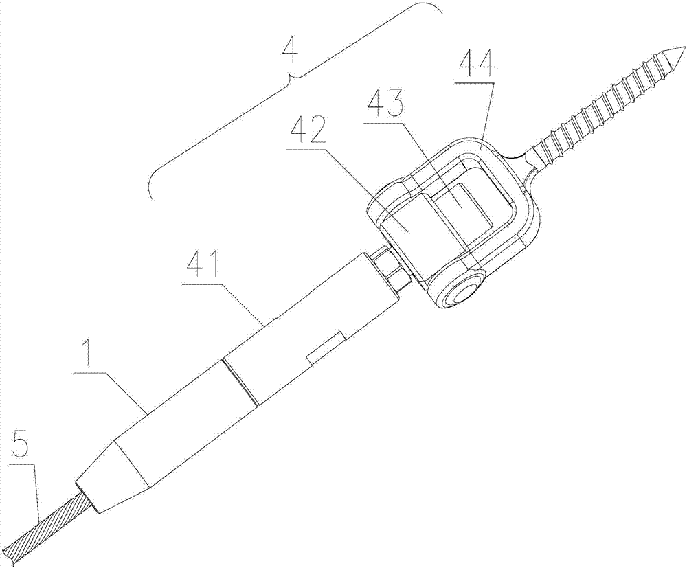
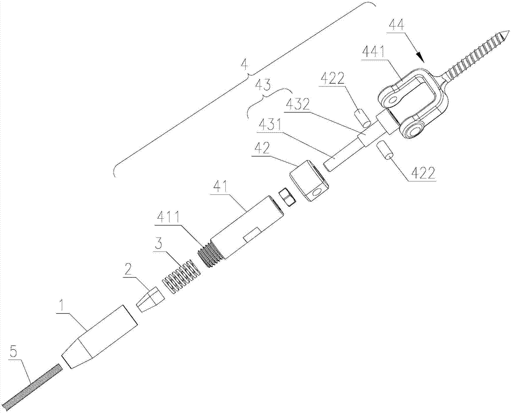
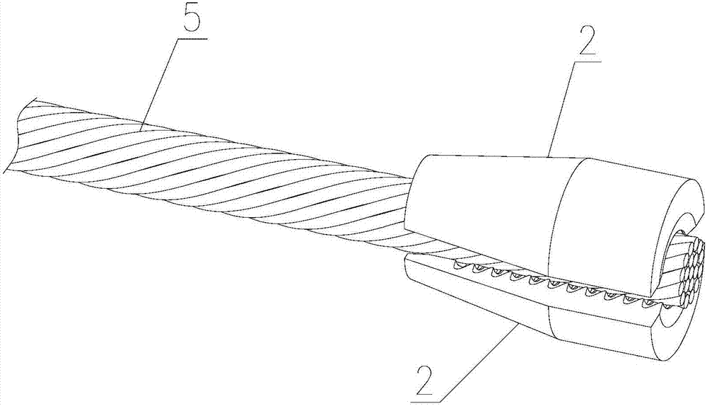
[0064] Such as Figure 1 to Figure 10 As shown, a guardrail cable fast locking device is used to be installed on the steel cable 5 adjacent to its end point and detachably fixed to the guardrail. The guardrail steel cable quick locking device includes: an outer sleeve 1, It has the same tapered through hole 11 and the first internally threaded hole 12, the aperture of the first internally threaded hole 12 is greater than or equal to the maximum aperture of the tapered through hole 11; tapered chuck 2, which has a The clamping hole 21 through which the steel cable 5 passes, and the clamping hole 21 is provided with a plurality of locking teeth 22, which are placed at the tapered through hole 11 of the outer sleeve 1; the elastic element 3, which is placed The bottom of the outer sleeve 1 inner tapered chuck 2; the installation and fixing mechanism 4 is fixedly installed on the guardrail, and the installation and fixing mechanism 4 is provided with a first external threaded rod ...

Embodiment approach 2

[0069] Such as Figure 11 to Figure 13 As shown, the second embodiment is basically the same as the first embodiment, except that the other end of the guardrail fixing member 44 is a screw, and a screw hole is provided on the guardrail, and the screw passes through the screw hole and is fixed on the guardrail with a nut.

Embodiment approach 3

[0071] Such as Figure 14 to Figure 16 As shown, a guardrail cable fast locking device is used to be installed on the steel cable 5 adjacent to its end point and detachably fixed to the guardrail. The guardrail steel cable quick locking device includes: an outer sleeve 1, It has the same tapered through hole 11 and the first internally threaded hole 12, the aperture of the first internally threaded hole 12 is greater than or equal to the maximum aperture of the tapered through hole 11; tapered chuck 2, which has a The clamping hole 21 through which the steel cable 5 passes, and the clamping hole 21 is provided with a plurality of locking teeth 22, which are placed at the tapered through hole 11 of the outer sleeve 1; the elastic element 3, which is placed The bottom of the outer sleeve 1 inner tapered chuck 2; the installation and fixing mechanism 4 is fixedly installed on the guardrail, and the installation and fixing mechanism 4 is provided with a first external threaded rod...


PUM


Abstract

The invention provides a guardrail steel cable quick locking device which is used for being installed on the portion, close to the end of a steel cable, of the steel cable and detachably fixed to a guardrail. The locking device comprises an outer sleeve, a conical chuck, an elastic component and an installing and fixing mechanism, wherein the outer sleeve is provided with a conical through hole and a first internal thread hole which are communicated with each other, and the hole diameter of the first internal thread hole is larger than or equal to the largest hole diameter of the conical through hole. The conical chuck is provided with a clamping hole used for the steel cable to pass, a plurality of clamping teeth are arranged in the clamping hole, and the conical chuck is placed in the conical through hole of the outer sleeve. The elastic component is placed at the bottom of the conical chuck in the outer sleeve. The installing and fixing mechanism is fixedly installed on the guardrail and provided with a first external threaded rod, the first external threaded rod is combined with the first internal thread hole in a screwed mode, and the elastic component is placed at the end of the first external threaded rod. The guardrail steel cable quick locking device can be installed upwards and downwards by 0-90 degrees, and the steel cable can freely rotate by 360 degrees. The guardrail steel cable quick locking device is enough in locking force, not prone to loosening after bearing external force, wide in applicability, convenient to install and high in work efficiency.

Description

technical field [0001] The invention relates to the technical field of guardrail protection products, in particular to a quick locking device for guardrail steel cables. Background technique [0002] The steel cable is used for the invisible installation of the home or the installation between the outdoor guardrail posts, and the cable tensioning device is required. The patent number is: US7198253, the U.S. patent that the title is called: WIRE ROPE CONNECTORS AND TENSIONERS FOR DECK RAILING SYSTEMS discloses a kind of guardrail cable tensioning device, and this guardrail steel cable tensioning device has the following disadvantages: 1. Locking force Not enough, it is easy to loosen under a little external force, and the maintenance cost is high; 2. The installation time is long, the labor cost is high, and the work efficiency is low; 3. The installation angle is only 0 to 45 degrees, and the environmental applicability is insufficient. [0003] In view of this, the present...

Claims


Application Information

Patent Timeline
Patent Type & Authority Patents(China)
IPC IPC(8): E04F11/18E04H17/00
CPCE04F11/1859E04H17/00
Inventor 林景在
Owner MODERN CO LTD
Why Eureka
Try Eureka