Long ornament member and method for manufacturing the same

a technology for ornament members and parts, applied in manufacturing tools, doors, roofs, etc., can solve the problems of increasing the manufacturing cost of ornament members, limiting the choice of cloth adhesion adhesives, and high cloth cost, so as to achieve the effect of considerably enhancing the decorativeness of the member

Active Publication Date: 2008-01-15
TOKAI KOGYO CO LTD
View PDF18 Cites 10 Cited by
  • Summary
  • Abstract
  • Description
  • Claims
  • Application Information

AI Technical Summary

Benefits of technology

[0008]The surface of the ornamental portion formed of vulcanized rubber is formed into an irregularly roughened surface due to the combination of the many fine microcapsules thermally expanded therein, the concave portions formed due to the burst of microcapsules provided on or in the vicinity of the surface, and the projection portions formed due to the swelling of the microcapsules provided on the surface. Thus, the ornament member provides an appearance closely resembling that of an actual woven cloth. The plural longitudinal or lateral convex ridges and / or the longitudinal or lateral concave grooves are formed on such a roughened surface of the ornamental portion in such a way as to extend along the longitudinal or lateral direction thereof. These longitudinal or lateral convex ridges and / or the longitudinal or lateral concave grooves are interrupted or deformed due to the interference by the concave portions and / or the projection portions, because of which the surface of the ornamental portion is formed into the roughened surface. The monotonous linearity of the longitudinal or lateral convex ridge and / or the longitudinal or lateral concave groove is changed, so that a surface pattern having fine ups and downs is formed. Consequently, the surface of the ornamental portion provides an appearance closely resembling that of a woven cloth, so that the decorativeness thereof is enhanced. Also, the ornamental portion, whose surface providing an appearance, which closely resembles that of a woven cloth, is formed integrally with the attaching portion.
[0048]The method of manufacturing a long ornament member according to the invention uses one of or the combination of the rubber extrusion die, in which the projections and / or the recesses are formed in the ornamental portion extrusion part (the inner surface of the flow path of the extrusion die) of the orifice thereof, and the roller, in the peripheral surface of which the projections and / or the recesses are formed. According to the method of the invention, preliminarily, the microcapsules are mixed and kneaded (or dispersed) in the material of the ornamental portion. Then, the material is extruded from the orifice and vulcanized. Thus, a long ornament member having a woven-fabric-like surface can easily be formed.

Problems solved by technology

However, the cost of the cloth is high.
Also, there is a limit to the choice of adhesive suitable for adhering the cloth.
Additionally, the adhesion process needs complex and troublesome control, which results in an increase in the manufacturing cost of the ornament member.

Method used


Image

  • Long ornament member and method for manufacturing the same
  • Long ornament member and method for manufacturing the same
  • Long ornament member and method for manufacturing the same

Examples


Embodiment Construction

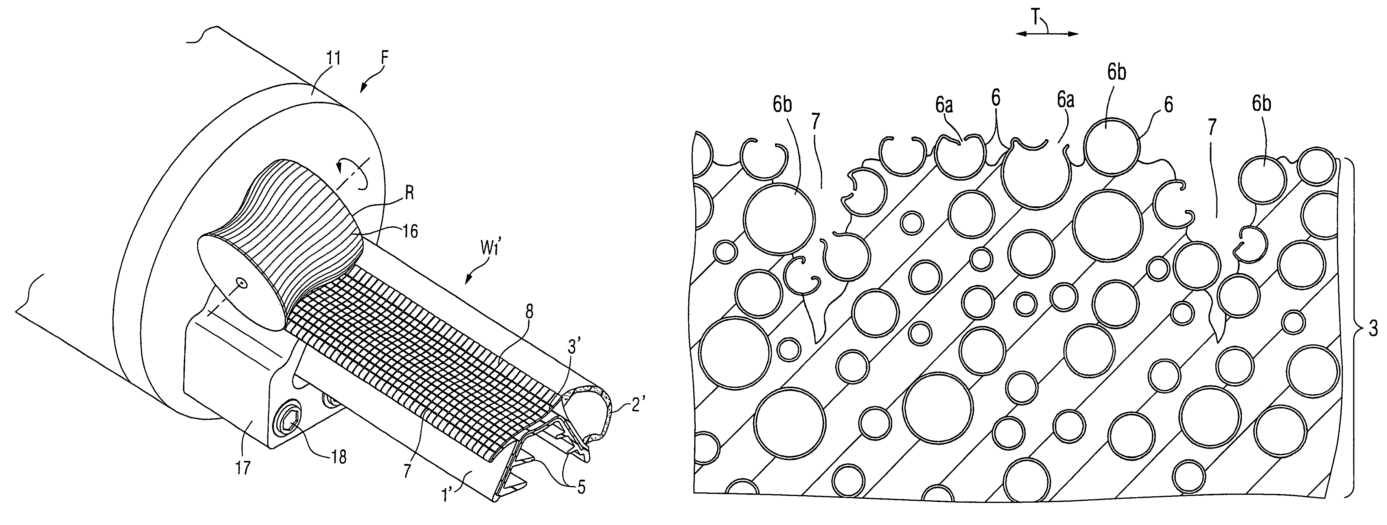
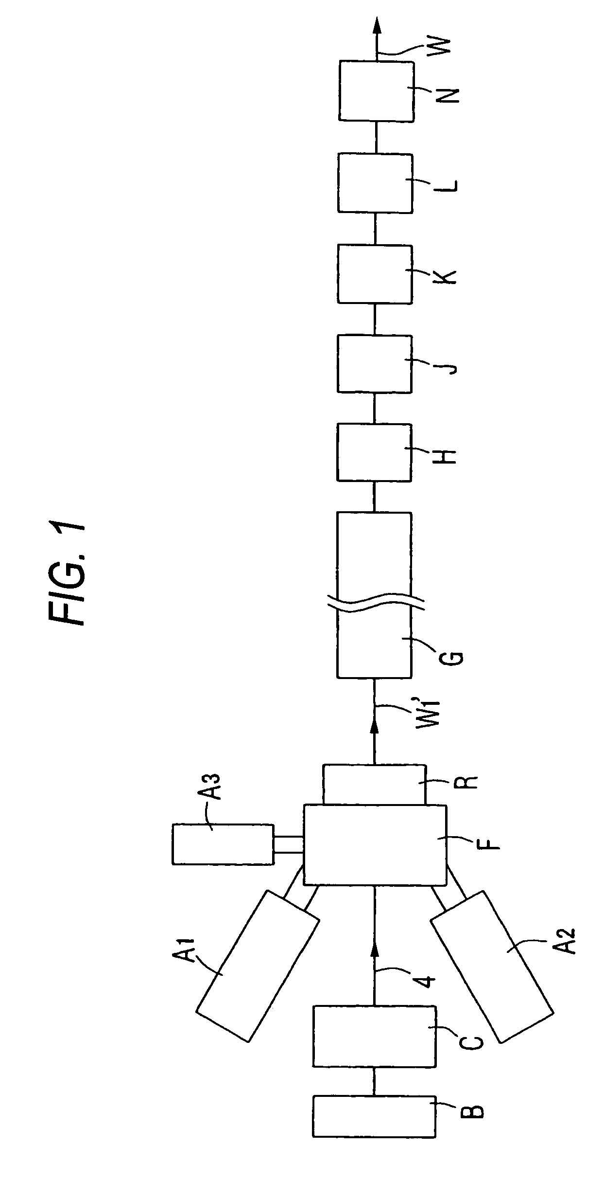
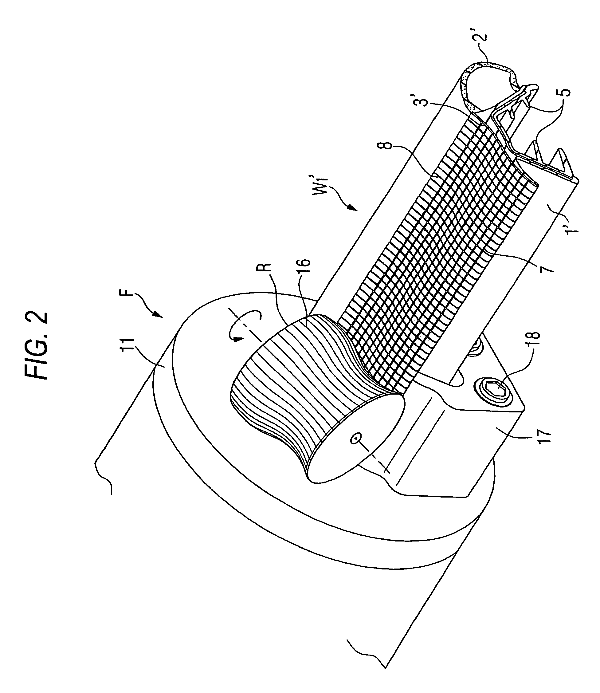
[0068]Hereinafter, the invention is described in detail with reference to a best mode for carrying out the invention and other modes. FIG. 1 is a schematic plan arrangement view illustrating a manufacturing apparatus including a rubber extrusion die F for carrying out the invention. FIG. 2 is a perspective view illustrating an outlet side part of the rubber extrusion die F. FIG. 3 is an elevational view viewed from the downstream side thereof. FIG. 4 is a cross-sectional view taken along line X-X in FIG. 3. First, a weather strip W1 will be described, and then an apparatus and a method of manufacturing the weather strip W1 will be described. Incidentally, in the case of describing the method of manufacturing the weather strip W1, the terms “predetermined attaching-portion forming part 1′,”“predetermined seal-portion forming part 2′,” and “predetermined ornamental-portion forming part 3′” are sometimes used in the process of molding for describing an attaching portion 1, a seal porti...


PUM

PropertyMeasurementUnit
heightaaaaaaaaaa
depthaaaaaaaaaa
diameteraaaaaaaaaa

Abstract

A long ornament member W1 has an attaching portion 1 and an ornamental portion 3 constituted by vulcanized rubber integrally formed on a surface of the attaching portion 1. The ornamental portion 3 has a surface roughened by plural microcapsules thermally expanded therein, plural concave portions 6a outwardly opened in the microcapsules 6 that burst on or in the vicinity of the ornamental portion 3, and plural projection portions 6b constituted by outwardly swelling the microcapsules 6 expanded in the vicinity of the surface. At least one of plural convex ridges and plural concave grooves are formed on the surface of the ornamental portion 3, the convex ridges extending along at least one of a longitudinal direction and a lateral direction that crosses the longitudinal direction, the concave grooves extending along at least one of the longitudinal direction and the lateral direction.

Description

TECHNICAL FIELD[0001]The present invention relates to a long ornament member having an ornamental portion that provides a woven fabric-like appearance and to a manufacturing method thereof.BACKGROUND ART[0002]Trimming members, such as a weather strip, which is attached along an opening edge of an opening / closing door of a vehicle like an automobile, for preventing rainwater from entering inside the vehicle, are cited as the long ornament member. An elongated sealing member to be inserted into and used for sealing the gap between one wall panel and an adjacent wall panel of a building is cited as another example of the long ornament member. It is usual that the ornament members, such as the weather strip and the sealing member, are elongatedly formed by extrusion-molding of kneaded black rubber, into which black carbon is mixed, and that the ornament member is produced by being cut to a predetermined length.[0003]Regarding the weather strip among the aforementioned trimming members, ...

Claims


Application Information

Patent Timeline
Patent Type & Authority Patents(United States)
IPC IPC(8): C08J9/38B60J10/02B29C35/02B29C48/17B29C48/21B29C48/30B29C48/35B29C48/49B29C59/04B29C69/02B60J10/00
CPCB29C47/0038B29C47/32B29C59/043B29C59/046B60J10/0005B60J10/0008B60J10/0031B60J10/0051B29C47/56B29C35/02B29C47/025B29C47/0033B29C47/0042B29K2021/00B29K2105/04B29K2105/048B29K2995/0072B29L2031/3005B29L2031/722B29C47/003B29C47/0057B29C47/0059B29C47/0061B29C47/0066B29C47/04B29C47/043B29C47/0019B60J10/24B60J10/16B60J10/17B60J10/265B29C48/07B29C48/12B29C48/13B29C48/001B29C48/0012B29C48/0018B29C48/0019B29C48/002B29C48/0022B29C48/154B29C48/16B29C48/17B29C48/35B29C48/49B29C48/21B30B11/18B60J10/00
Inventor HIROE, KEIJIFUKUSHIMA, YASUHIRO
Owner TOKAI KOGYO CO LTD
Why Eureka
Try Eureka