Medicant delivery system and method

a delivery system and a technology of a guide rod are applied in the field of delivering systems and methods of medicaments, which can solve the problems of difficult for a person inserting the tracheal tube to know where the leading end is, and the tracheal intubation is often done, so as to facilitate the positioning of the guide rod relative to the patient's trachea

Inactive Publication Date: 2008-01-22
P TECH
View PDF79 Cites 26 Cited by
  • Summary
  • Abstract
  • Description
  • Claims
  • Application Information

AI Technical Summary

Benefits of technology

[0009]It is believed that transmission of an image of body tissue adjacent to the leading end portion of the tracheal tube may advantageously be performed when the tracheal tube is utilized without benefit of the positioning apparatus. However, the transmission of an image of body tissue adjacent to the leading end portion of the tracheal tube may be performed when the positioning apparatus is used in association with the tracheal tube. Positioning of the guide rod relative to the patient's trachea may also be facilitated by the transmitting of images of body tissue adjacent to a leading end portion of the guide rod.

Problems solved by technology

Tracheal intubination is frequently done under emergency circumstances which are not optimal.
However, it is difficult for a person inserting the tracheal tube to know where the leading end portion of the tracheal tube is located relative to the patient's larynx.

Method used


Image

  • Medicant delivery system and method
  • Medicant delivery system and method
  • Medicant delivery system and method

Examples


second embodiment

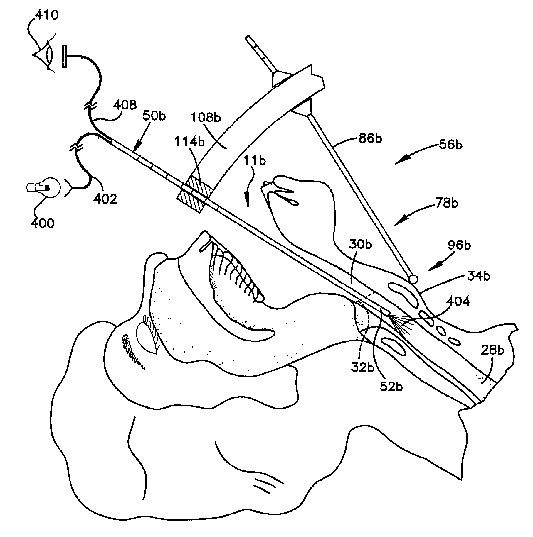
[0078]A second embodiment of the invention is illustrated in FIGS. 4 through 10. Since the embodiment of the invention illustrated in FIGS. 4-10 is generally similar to embodiment of the invention illustrated in FIGS. 1-3, similar terminology will be utilized to refer to similar components.

[0079]A portion of a patient's head 210 has been illustrated schematically in FIG. 4. The patient's head includes a mouth 212 which is connected with a throat 214 and a neck 216 of the patient. Although the patient's head 210 has been schematically illustrated in an upright orientation in FIG. 4, it should be understood that the patient's head could be in a different orientation if desired. For example, the patient's head 210 could be in the orientation illustrated in FIGS. 1 and 2 for the patient's head 10.

[0080]A pharynx 220 extends downward from a nasal cavity 222 in the head 210 of the patient. The pharynx 220 is connected with an esophagus 226 and a trachea 228 in the neck 216 of the patient....


PUM


Abstract

A tracheal tube positioning apparatus is located relative to a patient's trachea by engaging the patient's Adam's apple. Indicia on relatively movable sections of the positioning apparatus provides an indication of the distance between the patient's mouth and the patient's larynx. A flexible guide rod is moved through a distance corresponding to the distance between the patient's mouth and larynx, as determined by the positioning apparatus. A magnet is utilized to attract a leading end portion of the guide rod. A plurality of emitters may be disposed in an array around the patient's Adam's apple. Outputs from the emitters are detected by a detector connected with the guide rod and by a detector connected with the tracheal tube. Alternatively, a plurality of detectors may be disposed in an array around the patient's Adam's apple to detect the output from an emitter connected with the guide rod and by an emitter connected with the tracheal tube. Expandable elements may be connected with the guide rod and / or tracheal tube to steer movement along an insertion path.

Description

CROSS-REFERENCE TO RELATED APPLICATION[0001]This application is a continuation of U.S. patent application Ser. No. 09 / 728,553, filed on Dec. 2, 2000 now U.S. Pat. No. 6,820,614, the entire contents of which are incorporated by reference.FIELD OF THE INVENTION[0002]The present invention relates to a new and improved method and apparatus for use in tracheal intubination or other medical procedures.BACKGROUND OF THE INVENTION[0003]Tracheal intubination has previously been utilized to provide an unobstructed air passage to a patient's lungs. Tracheal intubination is frequently done under emergency circumstances which are not optimal. It has previously been recognized that is necessary to have a tracheal tube bend around the patient's epiglottis and move from the patient's pharynx into the larynx at the upper end of the patient's trachea rather than into the patient's esophagus. However, it is difficult for a person inserting the tracheal tube to know where the leading end portion of the...

Claims


Application Information

Patent Timeline
Patent Type & Authority Patents(United States)
IPC IPC(8): A61M16/00A61M16/04
CPCA61B8/0841A61B8/12A61B8/4263A61B8/445A61M25/0102A61M25/0108A61M25/09A61B1/07A61B1/0684A61B1/015A61B1/005A61B1/00124A61B1/00082A61B1/0676A61M16/0488A61M16/0434A61M16/0411A61M2025/09008A61M2025/0008A61M2025/091A61M16/0495A61M2025/022A61M16/0497A61B5/065A61B8/4254A61B8/461A61M2205/0272A61M2205/587
Inventor BONUTTI, PETER M.
Owner P TECH
Why Eureka
Try Eureka