Exhaust fan assembly having flexible coupling

a technology of flexible coupling and exhaust fan, which is applied in the field of exhaust fan, can solve the problems of increasing the wear on the motor, requiring people to enter an area polluted with contaminants, and expensive construction of exhaust stacks

Active Publication Date: 2008-01-22
GREENHECK FAN
View PDF94 Cites 66 Cited by
  • Summary
  • Abstract
  • Description
  • Claims
  • Application Information

AI Technical Summary

Problems solved by technology

In building such as laboratories, fumes are produced by chemical and biological processes, which may have an unpleasant odor, is noxious or toxic.
Such exhaust stacks, however, are expensive to build and are unsightly.
Unfortunately, the bearings that support the motor shaft inside the motor absorb the thrust loads imparted by the fan during operation, thus increasing wear on the motor.
Furthermore, because the interface between the motor shaft and the fan is located in an area that receives exhaust air during operation, a person is required to enter an area that is polluted with contaminants when motor maintenance operations involve detachment of the motor shaft from the fan.

Method used


Image

  • Exhaust fan assembly having flexible coupling
  • Exhaust fan assembly having flexible coupling
  • Exhaust fan assembly having flexible coupling

Examples


second embodiment

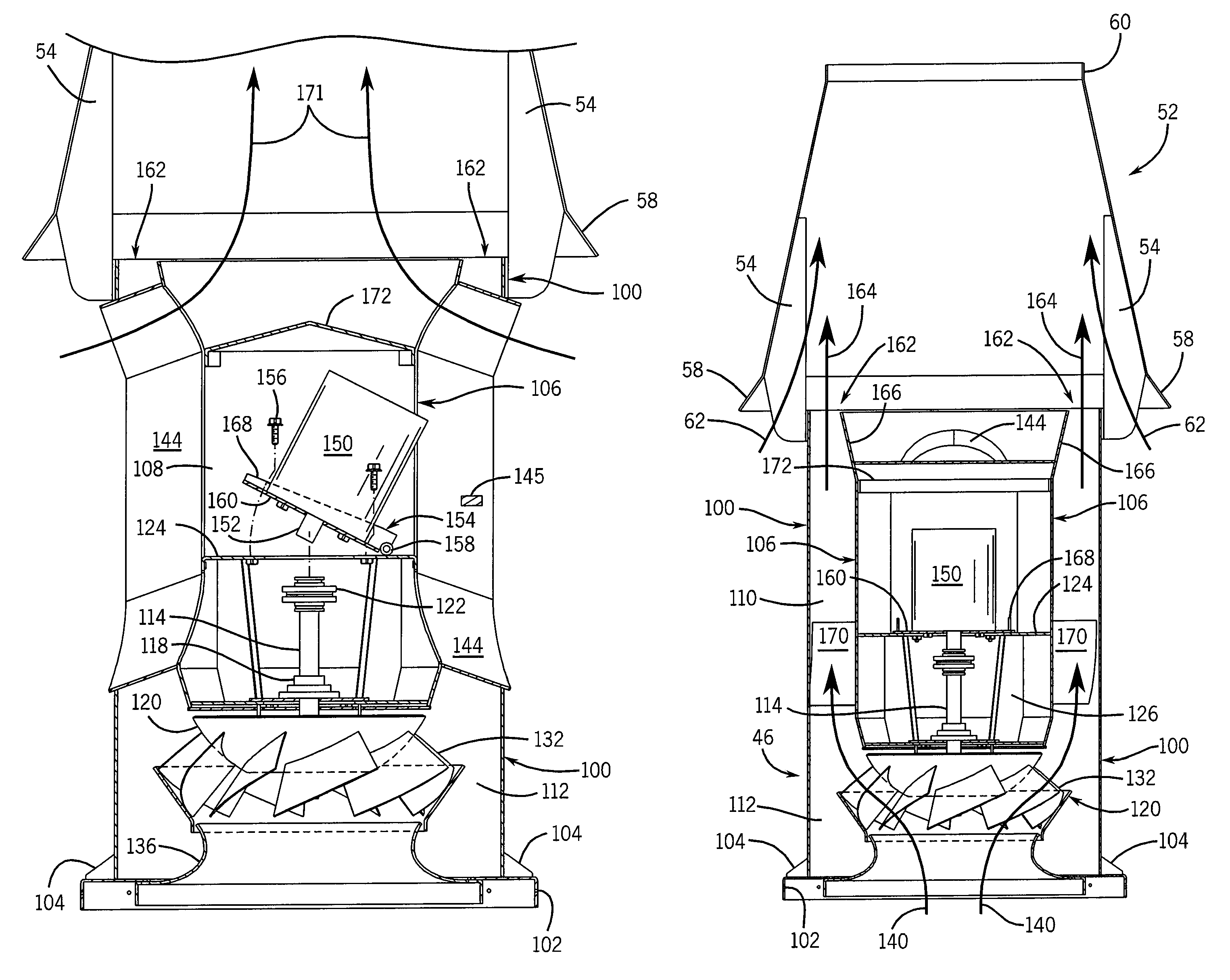
[0086]Referring particularly to FIGS. 18 and 19, an alternative embodiment of the invention is substantially the same as the preferred embodiment described above except the nozzle end of the fan assembly 46 is modified to add an additional, second nozzle assembly 50. In this second embodiment the outer wall 100 of the fan assembly is tapered radially inward at its upper end to form a first nozzle 53 with the inner wall 106 which extends straight upward, beyond the nozzle 53. The second nozzle assembly 50 is a frustum-shaped element which is fastened to the extended portion of the inner wall 106 by brackets 55. It is flared around its bottom end to form an inlet bell 57 similar to that on the windband 52. The second nozzle assembly 50 is concentric about the inner wall 106, and its top end is coplanar with the top end of the inner wall 106 to form an annular-shaped second nozzle 59 therebetween. Brackets 61 fasten around the perimeter of the second nozzle assembly 50 and extend upwar...

first embodiment

[0087]Referring particularly to FIG. 19, the annular space between the lower end of the second nozzle assembly 50 and the outer wall 100 forms a first gap through which ambient air enters as indicated by arrows 63. This air is entrained with the swirling exhaust air exiting the first nozzle 53 to dilute it. Similarly, the annular space between the lower end of the windband 52 and the second nozzle assembly 50 forms a second gap through which ambient air enters as indicated by arrows 65. This air is entrained with the once diluted exhaust air exiting the second nozzle 59 to further dilute the exhaust. As with the first embodiment, further ambient air which enters through the passageways and flows out the top end of the inner wall 106 as shown in FIG. 18 by arrow 67 also dilutes the exhaust before it is expelled at high velocity out the exhaust outlet at the top of the windband 52.


PUM


Abstract

An exhaust assembly is provided for expelling contaminated air from a building. The assembly includes a plenum, a fan assembly attached to the plenum, and a windband mounted on top of the fan assembly. The fan assembly is constructed of cylindrical outer and inner walls which define a drive chamber and surrounding annular space. A fan driven by a motor whose shaft extends downward from the drive chamber draws exhaust air from the plenum and blows it up through the annular space to a nozzle at the top of the fan assembly. The motor is pivotally mounted inside the assembly to provide access to the motor components when it is desired to perform inspection and maintenance.

Description

CROSS REFERENCE TO RELATED APPLICATIONS[0001]This is a continuation-in-part of U.S. patent application 10 / 924,532 filed Aug. 24, 2004, and further claims the benefit of U.S. Provisional Patent Application No. 60 / 537,609 filed Jan. 20, 2004, and further claims the benefit of U.S. Provisional Patent Application No. 60 / 558,074 filed Mar. 30, 2004, the disclosure of each of which is hereby incorporated by reference as if set forth in their entirety herein.BACKGROUND OF THE INVENTION[0002]The present invention relates generally to exhaust fans, and more particularly to exhaust fans of the type that draw contaminated air from one or more fume hoods dispersed throughout a building, mix the contaminated air with ambient air to dilute the contaminants, and vent the diluted air from the building into the ambient environment.[0003]There are many different types of exhaust systems for buildings. In most of these the objective is to simply draw air from inside the building in an efficient manner...

Claims


Application Information

Patent Timeline
Patent Type & Authority Patents(United States)
IPC IPC(8): B05B15/12B08B15/00F04D25/02F24F7/02
CPCB08B15/002F04D25/02F24F7/025
Inventor SELIGER, MICHAEL GLENNHRDINA, TERRY LEEKOEPPEL, SCOTT JAMES
Owner GREENHECK FAN
Why Eureka
Try Eureka