Flexible wrist for surgical tool

a wrist mechanism and surgical technology, applied in the field of surgical tools, can solve the problems of reducing the cost of hospital residency, saving millions of hospital days, and millions of dollars annually in hospital residency costs alone, and reducing the cost of hospitalization

Inactive Publication Date: 2008-01-22
INTUITIVE SURGICAL OPERATIONS INC
View PDF21 Cites 304 Cited by
  • Summary
  • Abstract
  • Description
  • Claims
  • Application Information

AI Technical Summary

Benefits of technology

[0020]In accordance with an aspect of the present invention, a wrist mechanism includes a minimally invasive surgical instrument comprises an elongate shaft having a working end, a proximal end, and a shaft axis between the working end and the proximal end; and an end effector. A wrist member has a flexible tube and an inner spring which include proximal portions connected to the working end of the elongate shaft and distal portions connected to the end effector. The inner spring is disposed inside an interior cavity of the flexible tube, and has an axis which is parallel to an axis of the flexible tube. A plurality of actuation cables (or wires) have distal portions connected to the end effector and extend from the distal portion through the wrist member toward the elongate shaft to proximal portions which are actuatable to bend the wrist member in pitch rotation and yaw rotation. If actuation wires are used they may also help support the end effector.

Problems solved by technology

Thus, an increased adoption of minimally invasive techniques could save millions of hospital days, and millions of dollars annually in hospital residency costs alone.
There are many disadvantages relating to current minimally invasive surgical (MIS) technology.
For example, existing MIS instruments deny the surgeon the flexibility of tool placement found in open surgery.
Most current laparoscopic tools have rigid shafts, so that it can be difficult to approach the worksite through the small incision.
Additionally, the length and construction of many endoscopic instruments reduces the surgeon's ability to feel forces exerted by tissues and organs on the end effector of the associated tool.
The lack of dexterity and sensitivity of endoscopic tools is a major impediment to the expansion of minimally invasive surgery.

Method used


Image

  • Flexible wrist for surgical tool
  • Flexible wrist for surgical tool
  • Flexible wrist for surgical tool

Examples


Embodiment Construction

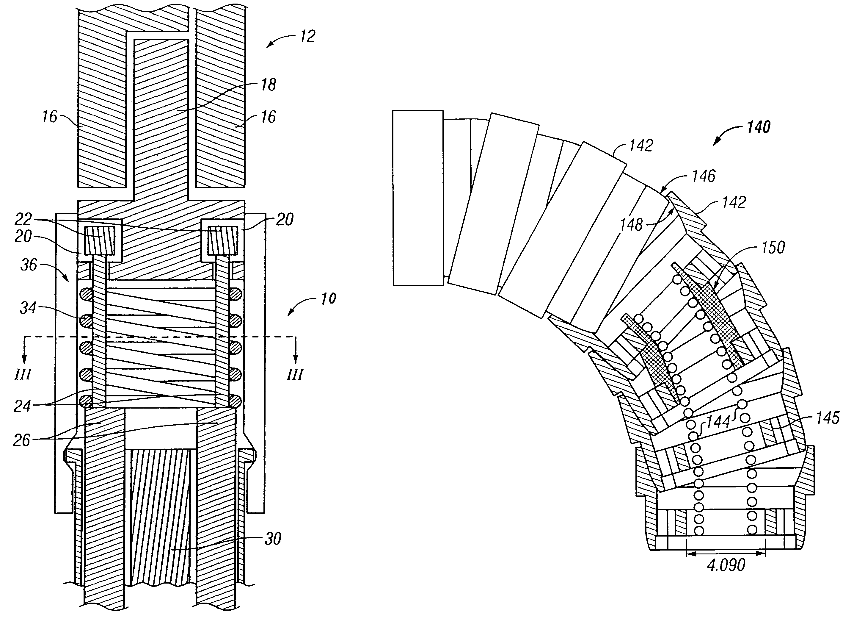
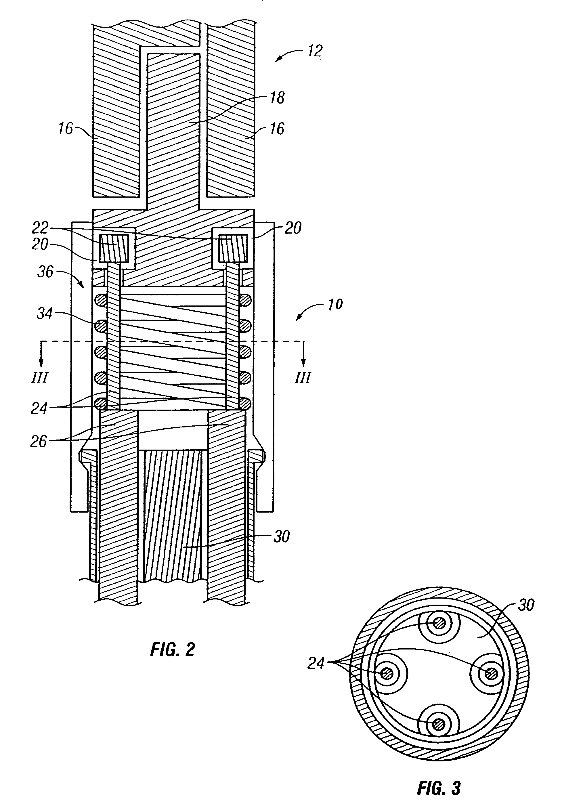
[0058]As used herein, “end effector” refers to an actual working distal part that is manipulable by means of the wrist member for a medical function, e.g., for effecting a predetermined treatment of a target tissue. For instance, some end effectors have a single working member such as a scalpel, a blade, or an electrode. Other end effectors have a pair or plurality of working members such as forceps, graspers, scissors, or clip appliers, for example. In certain embodiments, the disks or vertebrae are configured to have openings which collectively define a longitudinal lumen or space along the wrist, providing a conduit for any one of a number of alternative elements or instrumentalities associated with the operation of an end effector. Examples include conductors for electrically activated end effectors (e.g., electrosurgical electrodes; transducers, sensors, and the like); conduits for fluids, gases or solids (e.g., for suction, insufflation, irrigation, treatment fluids, accessory...


PUM


Abstract

The present invention is directed to a tool having a wrist mechanism that provides pitch and yaw rotation in such a way that the tool has no singularity in roll, pitch, and yaw. In one embodiment, a minimally invasive surgical instrument comprises an elongate shaft having a working end, a proximal end, and a shaft axis between the working end and the proximal end; and an end effector. A wrist member has a flexible tube including an axis extending through an interior surrounded by a wall. The wall of the flexible tube includes a plurality of lumens oriented generally parallel to the axis of the flexible tube. The wrist member has a proximal portion connected to the working end of the elongate shaft and a distal portion connected to the end effector. A plurality of actuation cables have distal portions connected to the end effector and extend from the distal portion through the lumens of the wall of the wrist member toward the elongate shaft to proximal portions which are actuatable to bend the wrist member in pitch rotation and yaw rotation.

Description

CROSS-REFERENCES TO RELATED APPLICATIONS[0001]This application is based on and claims the benefit of U.S. Provisional Patent Application No. 60 / 431,636, filed Dec. 6, 2002, the entire disclosure of which is incorporated herein by reference. This application is related to the following patents and patent applications, the full disclosures of which are incorporated herein by reference:[0002]U.S. patent application Ser. No. 10 / 187,248, entitled “Surgical Tool Having Positively Positionable Tendon-Actuated Multi-Disk Wrist Joint,” filed on Jun. 28, 2002;[0003]U.S. patent application Ser. No. 10 / 186,176, entitled “Platform Link Wrist Mechanism”, filed on Jun. 28, 2002;[0004]PCT International Application No. PCT / US98 / 19508, entitled “Robotic Apparatus”, filed on Sep. 18, 1998, and published as W099 / 50721;[0005]U.S. patent application Ser. No. 09 / 418,726, entitled “Surgical Robotic Tools, Data Architecture, and Use”, filed on Oct. 15, 1999;[0006]U.S. patent application Ser. No. 60 / 111,711,...

Claims


Application Information

Patent Timeline
Patent Type & Authority Patents(United States)
IPC IPC(8): A61B17/28A61BA61B1/00A61B1/005A61B1/008A61B1/018A61B17/00A61B17/04A61B17/068A61B17/128A61B17/42A61B18/14A61B19/00
CPCA61B1/00142A61B1/00149A61B1/0058A61B1/008A61B1/018A61B17/062A61B17/068A61B17/1285A61B17/29A61B18/1442A61B2017/003A61B2017/00309A61B2017/2901A61B34/71A61B2034/305A61B2034/306A61B34/30A61B17/42A61B17/00
Inventor COOPER, THOMAS G.ANDERSON, S. CHRISTOPHER
Owner INTUITIVE SURGICAL OPERATIONS INC
Why Eureka
Try Eureka