Anti jamming device for a vacuum hose

a technology of vacuum hose and anti-jamming device, which is applied in the direction of vehicle cleaning, cable arrangement between relatively moving parts, instruments, etc., can solve the problems of affecting the normal movement of the hose between extended and retracted positions, and prone to damage the hos

Inactive Publication Date: 2008-01-29
WHIRLPOOL CORP
View PDF4 Cites 12 Cited by
  • Summary
  • Abstract
  • Description
  • Claims
  • Application Information

AI Technical Summary

Benefits of technology

[0009]In one aspect of the invention, a handle is mounted to the hose and is retained out of the cabinet when the hose is in the retracted position. The handle has a light, preferably, an LED. The handle can have a nozzle portion and a grip portion, with the nozzle portion angled relative to the grip portion. Ideally, the handle nests within a collar on a top wall of the cabinet, canted relative to the cabinet for ease of access.

Problems solved by technology

A problem with a driven hose in a vacuum system is that normal movement of the hose between extended and retracted positions can occasionally be obstructed, where the hose gets jammed.
Continued driving of the hose in such conditions risks damaging the hose.

Method used


Image

  • Anti jamming device for a vacuum hose
  • Anti jamming device for a vacuum hose
  • Anti jamming device for a vacuum hose

Examples


first embodiment

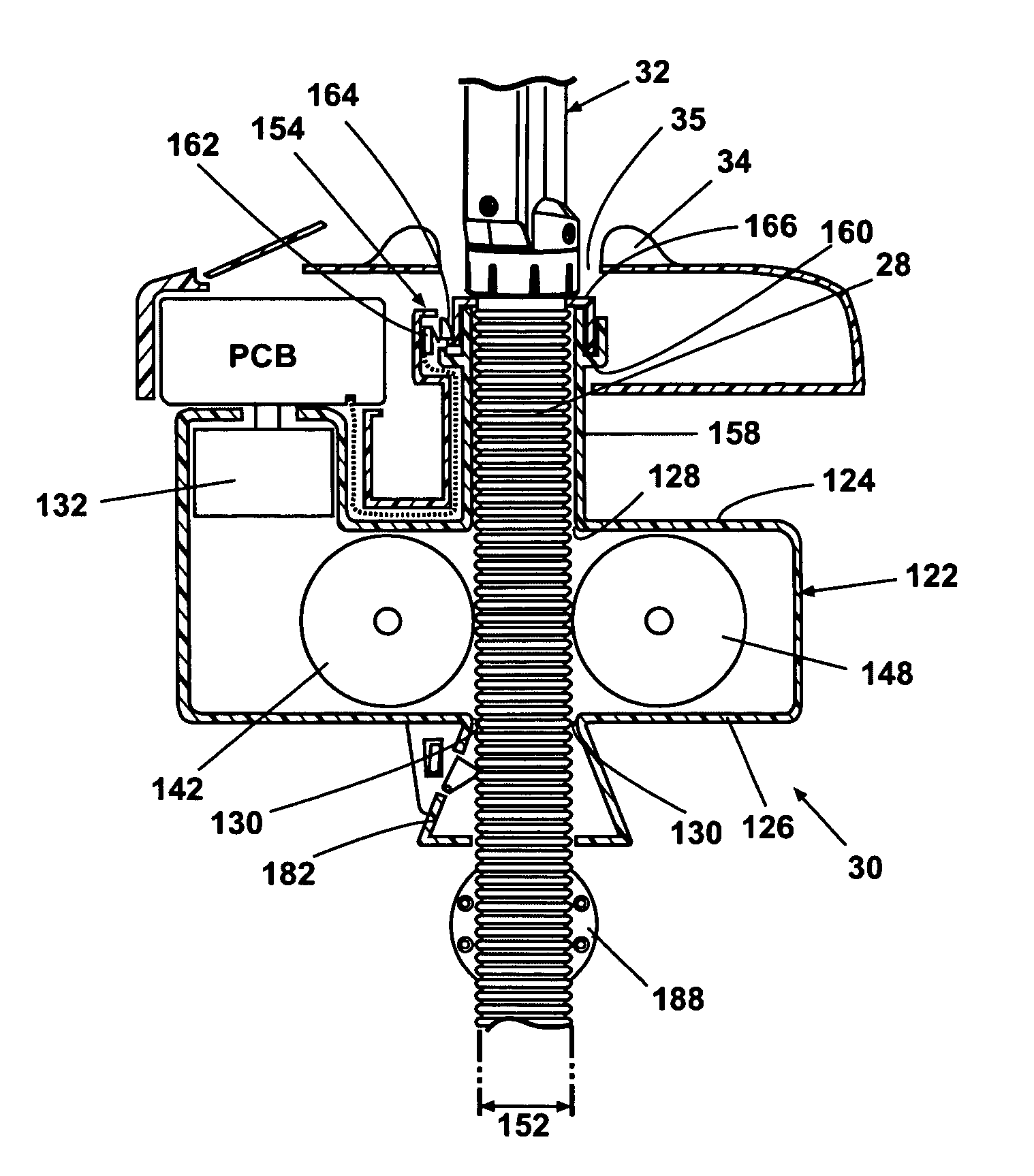
[0048]Exemplary embodiments of a retraction stop mechanism 154 and an extension stop mechanism 156 are illustrated in FIGS. 9 and 10. Looking at FIG. 9, an retraction stop mechanism 154 includes a hose conduit 158 extending upwardly from the upper aperture in the gearbox 122, and terminates in an annular slot 160 at or beneath the collar 34. A limit switch 162, preferably in the form of a microswitch, is mounted within the storage compartment 24 adjacent the annular slot 160. A trigger 164 is mounted within the annular slot 160 and movable between a first position where it engages the limit switch 162 and a second position where it does not engage the limit switch. The trigger 164 is preferably biased to the second position. The upper end of the vacuum hose 28 near the handle 32 carries an annular sleeve 166 sized to be received within the annular slot 160. When the annular sleeve 166 is nested within the annular slot 160, it urges the trigger 164 to the first position where it enga...

second embodiment

[0049]Looking now at FIG. 10, a retraction stop mechanism 154′ includes a hose conduit 158 extending upwardly from the upper aperture 128 in the gearbox 122. The hose conduit 158 terminates in an annular cup 170. A limit switch 172, preferably in a form of a microswitch, is mounted within the annular cup 170. A compression spring 174 extends upwardly from the bottom of the annular cup 170 and surrounds but does not engage the vacuum hose 28. A sleeve 176 is secured to the upper end of the compression spring 174, and has an open socket 178 at an upper end thereof. A nub 180 depends from the sleeve 176 outside the compression spring 174 in line to engage the limit switch 172 when the compression spring 174 is compressed, but not engage the limit switch 172 when the compression spring 174 is uncompressed. The open socket 178 is sized to contact the lower end of the handle 32, yet to allow the vacuum hose 28 to move freely through it. In operation, as the vacuum hose 28 approaches its r...


PUM


Abstract

A vacuum system has a cabinet that can be mounted to a wall. The cabinet includes a hose connectable to a vacuum source. The hose is extendible from the cabinet between extended and retracted positions. A rotatable shaft drives the hose and a power source causes the rotatable shaft to rotate. A sensor measures the speed of rotation of the shaft and signals a controller to stop the power source when the speed falls below a predetermined threshold.

Description

BACKGROUND OF THE INVENTION[0001]1. Field of the Invention[0002]The invention relates generally to vacuum systems, and more particularly to mechanisms for automatically driving vacuum hoses.[0003]2. Description of the Related Art[0004]Central vacuum systems where a vacuum hose can be reeled between extended and retracted positions are known. An example of such a hose driving system in a wall mounted central vacuum system is found in U.S. Pat. No. 5,740,581 to Harrelson, II. A problem with a driven hose in a vacuum system is that normal movement of the hose between extended and retracted positions can occasionally be obstructed, where the hose gets jammed. Continued driving of the hose in such conditions risks damaging the hose. There is a need to detect when a jam condition occurs so that the driving mechanism can be terminated. It is known to measure the torque on an electric motor that drives a vacuum hose, and stop the motor when torque exceeds a predetermined value, assuming tha...

Claims


Application Information

Patent Timeline
Patent Type & Authority Patents(United States)
IPC IPC(8): A47L9/26
CPCA47L5/225A47L5/38A47L7/0038A47L7/0042A47L9/0027A47L9/0063A47L9/2805A47L9/2842A47L9/2889A47L9/2894A47L9/30A47L9/327Y02B40/82Y02B40/00
Inventor ZIMMERLE, JOHNNY W.CLINE, WYATT A.GILIKSON, DARREN J. W.GRIFFITHS, SIMON P.
Owner WHIRLPOOL CORP
Why Eureka
Try Eureka