Wireless receiver with anti-jamming

a receiver and wireless technology, applied in the field of wireless data communication networks, can solve the problems of slow convergence of adaptive filtering techniques, particularly problematic jamming, and sensitive wireless modems to unintentional jamming of high-power narrowband signals, so as to improve the anti-jamming performance of the transmitter/receiver pair, accurate estimation of transitions and other parameters of the jamming signal

Inactive Publication Date: 2006-08-24
INTEL CORP
View PDF13 Cites 45 Cited by
  • Summary
  • Abstract
  • Description
  • Claims
  • Application Information

AI Technical Summary

Benefits of technology

[0008] The phase detector operates most effectively in this manner when the jamming signal is strong, and this method is therefore preferably used when the strength of the jamming signal prevents sufficiently complete removal solely through the preceding approach of frequency “erasure.” Due to factors such as the finite length of the time window used in transforming the received signal to the frequency domain for demodulation, the effects of a strong jamming signal in a narrow band may be felt over a much wider range of frequencies in the receiver. Cancellation of the jamming signal before transformation to the frequency domain can help to overcome this problem.
[0009] Demodulating the jamming signal, when the method of modulation used in the jamming signal is known (for example, Frequency Shift Keying—FSK—modulation used for Bluetooth signals). The receiver can then accurately reconstruct the jamming signal in order to remove it from the processed signal. This approach is preferably used under the strongest jamming conditions.
[0012] In certain embodiments of the present invention, the phase detector used in determining the phase of the jamming signal comprises a phase-locked loop (PLL), preferably a digitally-implemented PLL. A buffer typically stores one or more blocks of samples of the incoming signal while the phase detector and jamming cancellation circuitry operates on the samples. This block-oriented mode of operation allows the PLL to be operated in non-causal fashion, running both forward and backward in time, in order to accurately estimate transitions and other parameters of the jamming signal. Alternatively, the phase detector may comprise a filter, such as a finite impulse response (FIR) or infinite impulse response (IIR) filter, with an automatic frequency control (AFC) circuit.
[0013] In further exemplary embodiments of the present invention, other techniques are used to improve the anti-jamming performance of a transmitter / receiver pair. In one such exemplary embodiment, when the receiver determines that a packet has been corrupted by jamming but that the packet header may nonetheless enable identification of the identity of the transmitter that sent the packet, the receiver sends a NACK (non-acknowledge) signal to the transmitter. The transmitter, upon receiving the NACK, retransmits the packet without back-off. Additionally or alternatively, an outer code is added to the transmitted data in each packet. Preferably, for the purpose of outer coding, each packet is divided into several code words, with Reed-Solomon codes.

Problems solved by technology

Wireless modems are sensitive to unintentional jamming by high-power narrowband signals in the communication band of the desired signal.
Jamming is particularly problematic in the 2.4 and 5.5 GHz bands, which have been set aside by the Federal Communications Commission (FCC) for unlicensed use.
Techniques of adaptive filtering, however, suffer from slow convergence and lack the capability to deal with transient in-band jamming.
Even using very fast adaptation, every such hop in an adaptive filtering system will generally cause a burst of errors in an COFDM or M-PSK receiver.

Method used


Image

  • Wireless receiver with anti-jamming
  • Wireless receiver with anti-jamming
  • Wireless receiver with anti-jamming

Examples


Embodiment Construction

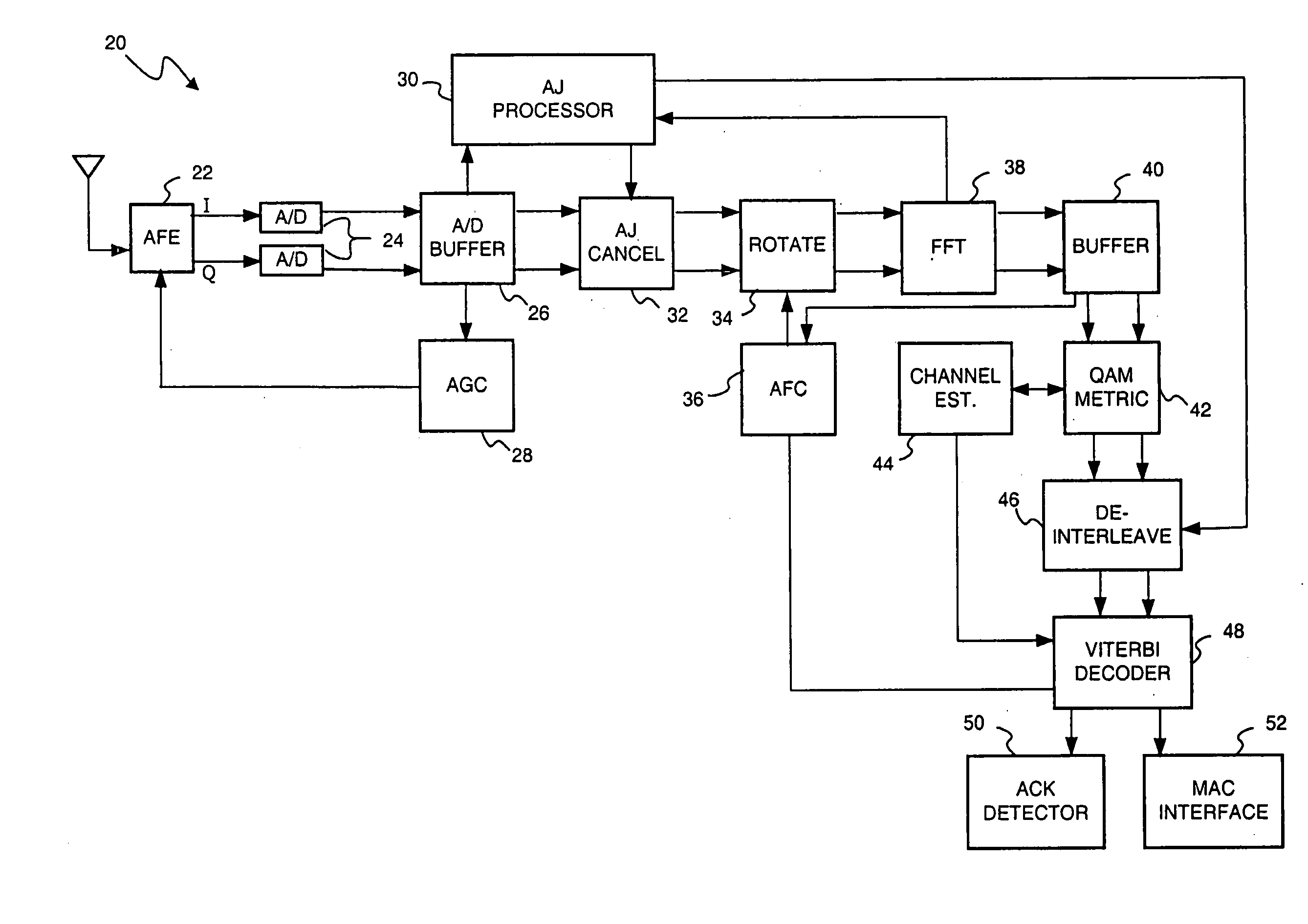
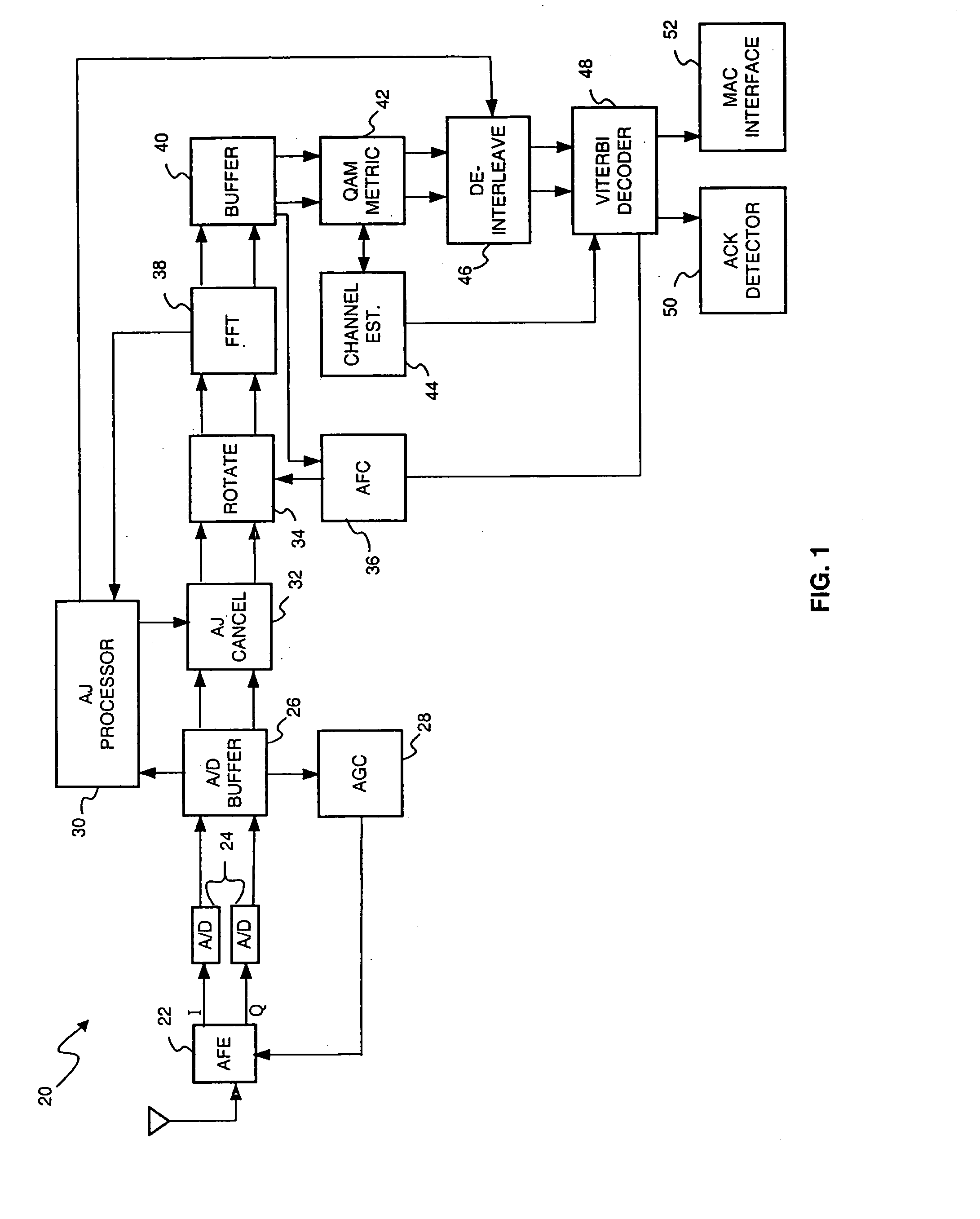
[0029]FIG. 1 is a block diagram that schematically illustrates a wireless receiver 20, in accordance with an exemplary embodiment of the present invention. In the description that follows, receiver 20 is assumed to be part of a modem used in a wireless LAN (WLAN), operating in accordance with an COFDM modulation scheme. Exemplary schemes of this sort are those put forth by IEEE standard 802.11a, including Annex G of the standard, as noted in the Background of the Invention. The WLAN environment is assumed to be noisy and, in particular, subject to jamming interference from a variety of possible sources, such as signals generated by Bluetooth transmitters. Although the elements of receiver 20 are shown and described in terms of separate functional blocks, it will be apparent to those skilled in the art that many or even all of these blocks may be implemented in a single integrated circuit chip or in a set of such chips. Additionally or alternatively, the digital processing functions ...


PUM


Abstract

An embodiment of the present invention provides a receiver capable of receiving a signal carrying data in the presence of jamming interference, the receiver comprising an anti-jamming (AJ) processor, adapted to process the received signal so as to determine a frequency, phase and amplitude of the jamming interference, a jamming cancellation circuit, coupled to the AJ processor, removes the jamming interference from the received signal responsive to the frequency, phase and amplitude determined by the AJ processor, and a demodulator, adapted to demodulate the signal after removal of the jamming interference therefrom so as to recover the data.

Description

CROSS-REFERENCE TO RELATED APPLICATIONS [0001] This U.S. patent application is a continuation of U.S. patent application Ser. No. 10 / 094,028 filed Mar. 28, 2002, which claims the benefit of U.S. Provisional Patent Application No. 60 / 274,499, filed Mar. 9, 2001, and No. 60 / 297,862, filed Jun. 13, 2001. Both of these provisional applications are incorporated herein by reference.FIELD OF THE INVENTION [0002] The present invention relates generally to wireless data communication networks, and specifically to receivers for wireless local area networks that must operate in the presence of jamming. BACKGROUND OF THE INVENTION [0003] Wireless local area networks (WLANs) are gaining in popularity, and new applications are being developed. The original WLAN standards, such as “Bluetooth” and IEEE 802.11, were designed to enable communications at 1-2 Mbps in a band around 2.4 GHz. More recently, IEEE working groups have defined the 802.11a and 802.11b extensions to the original standard, in or...

Claims


Application Information

Patent Timeline
Patent Type & Authority Applications(United States)
IPC IPC(8): H04K1/10H04K3/00H04L27/26
CPCH04K3/228H04L27/2647
Inventor ZEHAVI, EPHRAIMBETTESH, IDDO
Owner INTEL CORP
Why Eureka
Try Eureka