Chaotic optical time domain reflectometer method and apparatus

a reflectometer and time domain technology, applied in the field of correlation optical time domain reflectometers, can solve the problems of reducing the resolution of pulse-based otdrs, so as to avoid disadvantages, simple structure, and high resolution

Active Publication Date: 2010-11-18
TAIYUAN UNIV OF TECH
View PDF1 Cites 47 Cited by
  • Summary
  • Abstract
  • Description
  • Claims
  • Application Information

AI Technical Summary

Benefits of technology

[0006]The object of the invention is to provide a method and corresponding apparatus for performing optical time domain reflectometer which overcomes the tradeoff between the dynamic range and spatial resolution in conventional OTDR and avoids the disadvantages caused by the above-mentioned correlation OTDR. This method has merits of high resolution, simple structure and lower cost.

Problems solved by technology

While the drawback of such an OTDR technique is that its resolution is limited by the width of the optical pulse, which is generated by pulse laser as light source.
The dynamic range of the OTDR depends on the amount of energy that is launched into the fiber and is limited due to the available laser pulse peak power.
Increased pulse width reduces the resolution of the pulse-based OTDR.
To enhance the dynamic range, the resolution will be reduced accordingly, and vise versa, which has become an inextricable problem for the pulse-based OTDR.
However, fail to make full use of the advantages of the correlation technology; the resolution is still limited by the bandwidth of the electrical codes.
The unambiguous detection span is also limited due to the repeat waveform of pseudorandom codes.
Also, complex devices, such as pseudorandom codes generator and encoding and modulation circuits, are needed.

Method used


Image

  • Chaotic optical time domain reflectometer method and apparatus
  • Chaotic optical time domain reflectometer method and apparatus
  • Chaotic optical time domain reflectometer method and apparatus

Examples


embodiment one

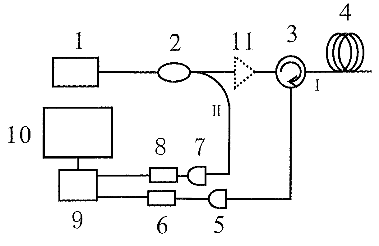
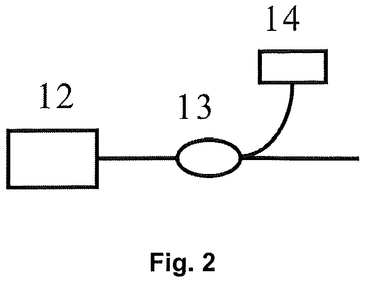
[0046]FIG. 1 schematically depicts a chaotic OTDR according to the invention. The chaotic OTDR mainly comprises a chaotic laser transmitter 1, a fiber coupler 2, an optical circulator 3, two photodetectors 5, 7, two A / D converters 6, 8, a signal processing device 9 and a display device 10.

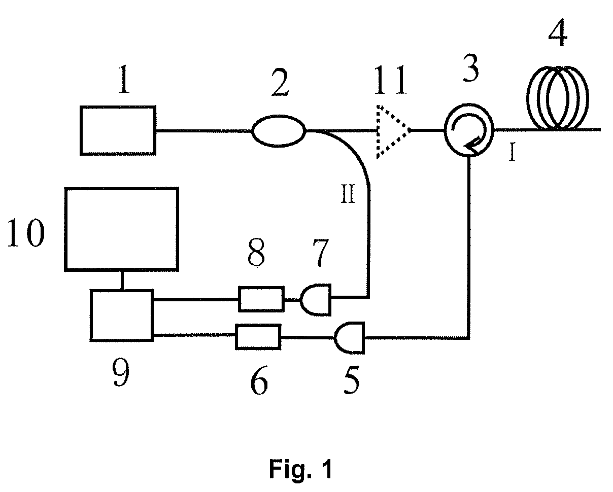
[0047]Further details of the chaotic laser transmitter 1 are explained below with reference to FIG. 2. The chaotic laser transmitter 1 is formed of a semiconductor laser 12, a fiber coupler 13, and a feedback section 14. The feedback section 14 is a digital reflector or an optical fiber with coated reflective film end or a fiber grating connected to a variable optical attenuator. In a semiconductor laser 12 with optical feedback, complex high dimensional chaotic output can be obtained by adjusting the controllable operational parameters of the feedback device 14. Alternatively, the feedback device 14 can be replaced by another semiconductor laser which is used as an injection laser, the chaotic las...

embodiment two

[0050]FIG. 1 also depicts the correlation method of the chaotic OTDR and further details are explained below. The chaotic laser signal emitted by the chaotic laser transmitter 1 is split into the probe signal I and the reference signal II. The back reflected probe signal Ig(t) is a time-delayed version of the reference signal II f(x) and can be written as: g(t)=Kf(t−τ0). Here τ0 is the delay time and K is the loss factor. The back reflected probe signal I g(t) and the delayed reference signal II f(x−τ) are provided to the signal processing device 9 that realizes fault location of the test fiber by correlating two received signals. The result output is then displayed on a display device 10. The cross correlation function I(τ) between f(x) and g(t) is given by:

I(τ)=K∫−∞+∞f(t−τ)f(t−τ0)dt

[0051]From the position of peak of the correlation trace, the fault is located. FIG. 4 shows the cross-correlation traces, which are obtained by correlating the reference signal f(x) with the back-refl...


PUM

PropertyMeasurementUnit
wavelengthaaaaaaaaaa
electrical signalsaaaaaaaaaa
lengthaaaaaaaaaa

Abstract

In a method and a corresponding apparatus for performing chaotic optical time domain reflectometer, the chaotic laser signal, generated by the chaotic laser transmitter, is split into probe signal I and reference signal II by a fiber coupler. Through an optical circulator, the probe signal I is launched into the test fiber and the echo light is converted into electrical signal by a photodetector and digitalized by an A/D converter. The reference signal II is converted into electrical signal by a photodetector and digitalized by another A/D converter. Two digital signals received from two A/D converters are correlated in a signal processing device to locate the exact position of faults in fibers. The result output is then displayed on a display device. This invention was developed to overcome the tradeoff between resolution and dynamic range of the pulse-based OTDR. This method can improve the dynamic range and spatial resolution significantly; enhance the anti-jamming capability and noise tolerance. Also it has merits of simple structure and lower cost.

Description

FIELD OF THE INVENTION[0001]This invention relates to a method and apparatus for carrying out optical time domain reflectometer, and more particularly to the correlation optical time domain reflectometer in which the chaotic laser is used as the probe signal. More generally, this invention is in the field of monitoring optical transmission line and optical fiber networks.BACKGROUND OF THE INVENTION[0002]Optical time domain reflectometer (OTDR) is a measuring device based on the backscatted or back-reflected signals. It's the most important tool for locating the fiber faults and estimating the fiber's length and overall attenuation, including splice and mated-connector losses. It can measure fiber by a non-destructive means and has a wide range of application in the field of optical fiber industry like optical fiber research and manufacturing, optical fiber networks installation and maintenance, playing a very important role in the fiber industry.[0003]Normally OTDR comprises four un...

Claims


Application Information

Patent Timeline
Patent Type & Authority Applications(United States)
IPC IPC(8): G01N21/88G06F15/00
CPCG01M11/3118G01B11/02
Inventor WANG, YUNCAIHE, HUCHENGWANG, BINGJIEWANG, ANBANG
Owner TAIYUAN UNIV OF TECH
Why Eureka
Try Eureka