
Eureka
For R&D, Eureka makes reading and utilizing patents & technical documents easy.
Eureka AIR
Designed for self-driven R&D workflows. Generate viable solutions, solve complex R&D challenges, empower your innovation with AI.

Eureka Materials
Designed for material experts only. Revolutionize your material R&D, from search, analyze, to developing new materials.

TechResearch
Generate reliable direction feasibility study reports for your R&D in just a few steps.

TechSeek
Discover and master advanced knowledge NOW. Basics, ideas, possibilities, all at once.

TechMind
As an expert in R&D Theories, TechMind can generates customized viable solutions instantly.

TechRisk
Analyze your overall solution with one click, know your potential R&D risks in advance.

TechMonitor
Get weekly tech updates, stay abreast of the latest tech innovations and key insights.
Spinal adjusting device and method
- Summary
- Abstract
- Description
- Claims
- Application Information
AI Technical Summary
Problems solved by technology
Method used
Image

Examples
Embodiment Construction
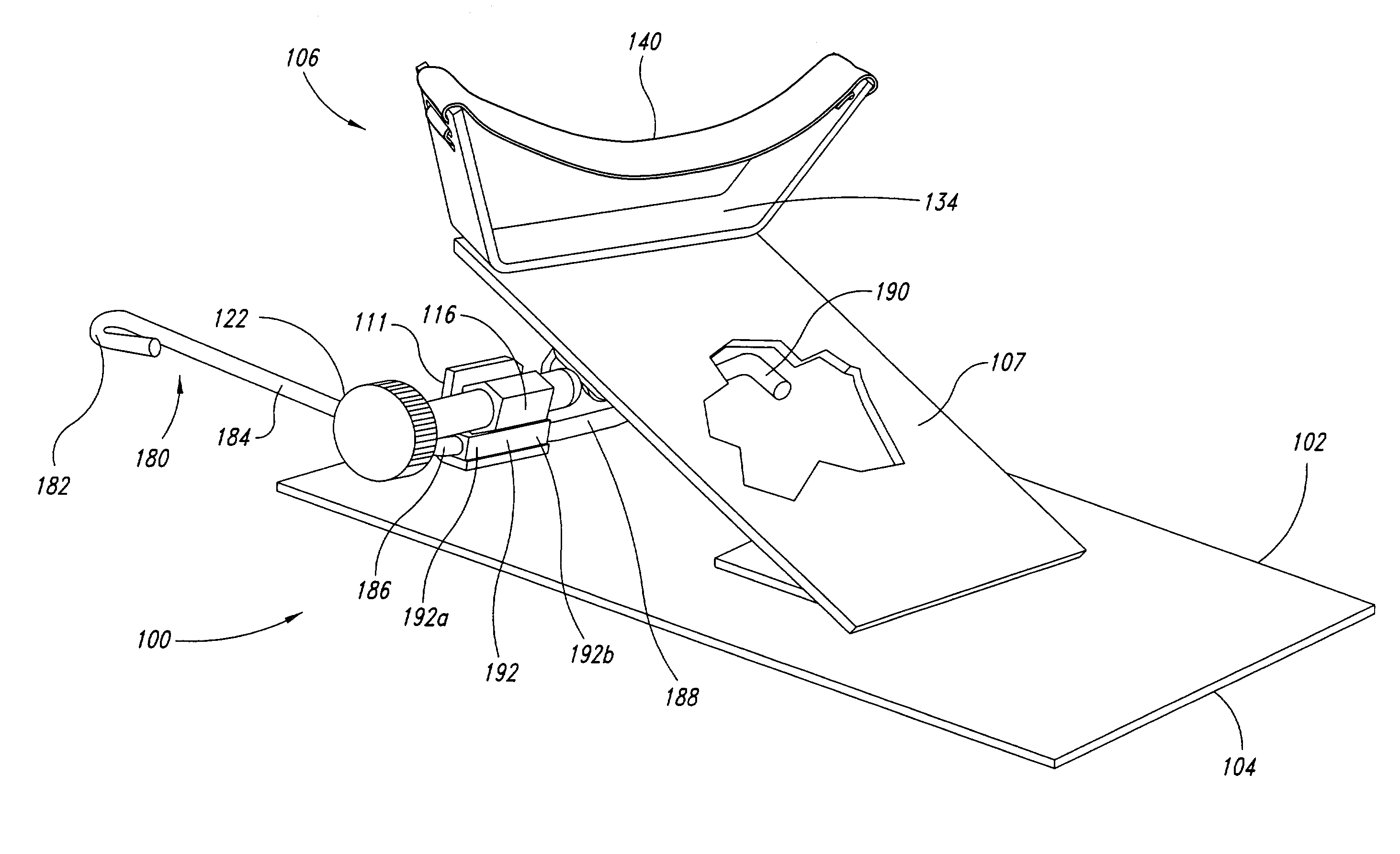
[0026]Referring initially to FIGS. 5-7B, shown therein is a spinal adjusting device 100, including a base plate assembly 102 (shown in FIG. 5) for use with a patient 103. In FIG. 5 is shown the components of the base plate assembly 102. The base plate assembly 102 includes a base plate 104, ideally made of ⅛th inch steel plate. In one embodiment the base plate 104 has dimensions of 10 inches wide and 12 inches long.
[0027]One half 105a of a pin hinge 105 is welded in the center of the base plate 104 for attachment of an upper plate assembly 106 with a pin 108. A tension adjustable drop assembly 110 is welded or otherwise affixed to the center of the forward end 104a of the base plate 104. In one embodiment, the drop assembly 110 is ideally made of a 1½×1½×⅛ inch thick angle plate 111. There is a ½ inch wide slot 112 milled in the center of the upright angle plate 111. There is a ¼ inch hole 114 drilled ½ inch to the right of the slot 112 and ½ inch from the top of the angle plate 111...
PUM
 Abstract
Description
Claims
Application Information
 - R&D Engineer
- R&D Manager
- IP Professional
- Industry Leading Data Capabilities
- Powerful AI technology
- Patent DNA Extraction
Browse by: Latest US Patents, China's latest patents, Technical Efficacy Thesaurus, Application Domain, Technology Topic, Popular Technical Reports.
© 2024 PatSnap. All rights reserved.Legal|Privacy policy|Modern Slavery Act Transparency Statement|Sitemap|About US| Contact US: help@patsnap.com