Multiring control method, node using the method, and control program

a control method and control program technology, applied in the field of multi-ring control methods, can solve problems such as the inability to protect the system, the network efficiency reduction, etc., and achieve the effect of efficient disposal

Inactive Publication Date: 2008-01-29
NEC CORP
View PDF5 Cites 43 Cited by
  • Summary
  • Abstract
  • Description
  • Claims
  • Application Information

AI Technical Summary

Benefits of technology

[0036]According to the present invention, the above-described arrangement ensures that a broadcast/multicast frame to be transferred o

Problems solved by technology

There is a possibility of the ring frame making one round or more of the relay ring, depending on the initial setting of the TTL counter, that is, the same ring frame may be transmitted two or more times to the ring node which is to receive the ring frame, resulting in a reduction in network efficiency.
If, in a similar network, a fault occurs at one of inter-ring bridge nodes connected between a plurality of rings when

Method used


Image

  • Multiring control method, node using the method, and control program
  • Multiring control method, node using the method, and control program
  • Multiring control method, node using the method, and control program

Examples


first embodiment

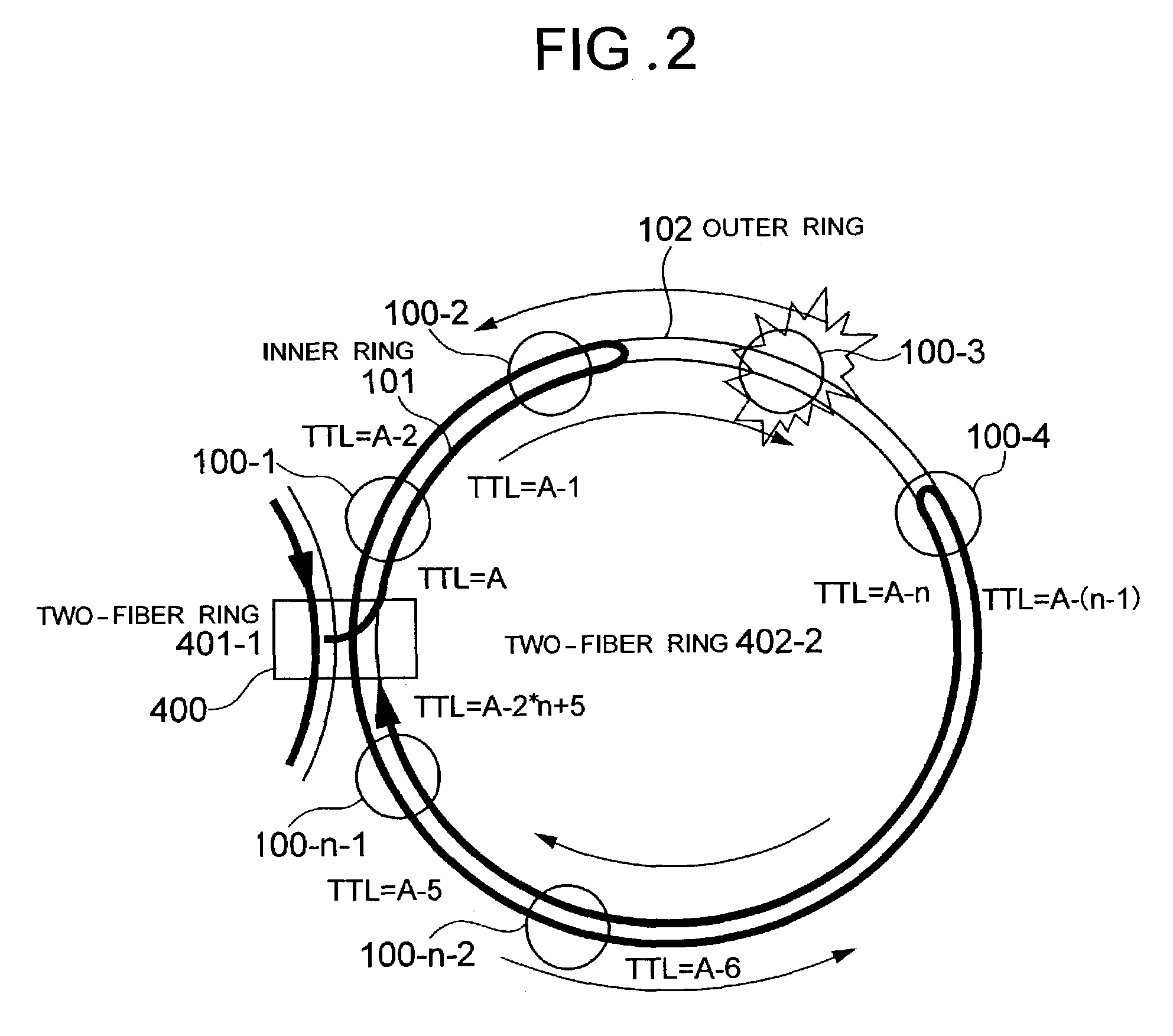
[0057]A first method for efficient discard of a ring frame in a relay ring will be described with reference to FIGS. 1 and 2 and also to the flowchart of FIG. 12 showing the operation of the first embodiment.

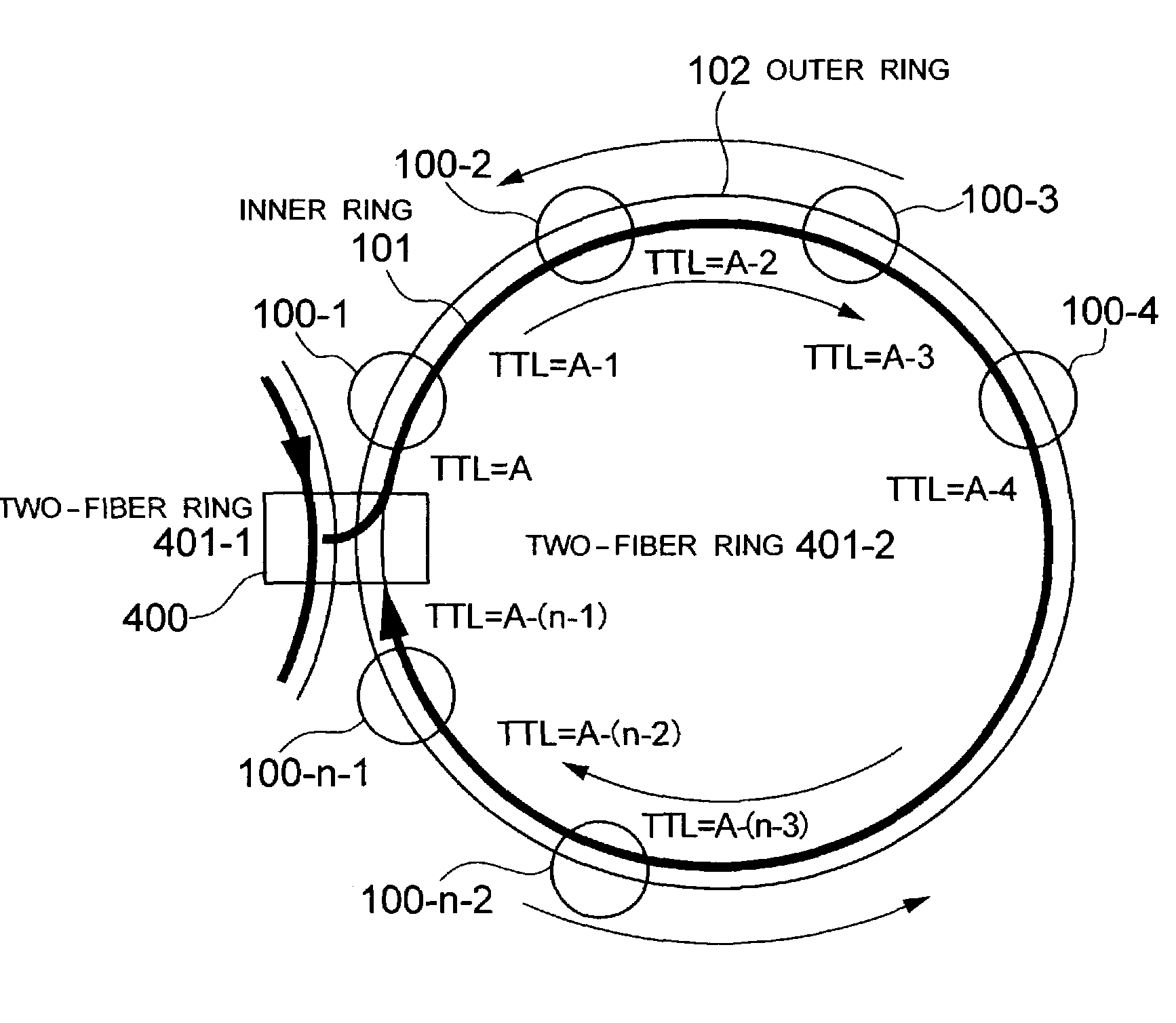
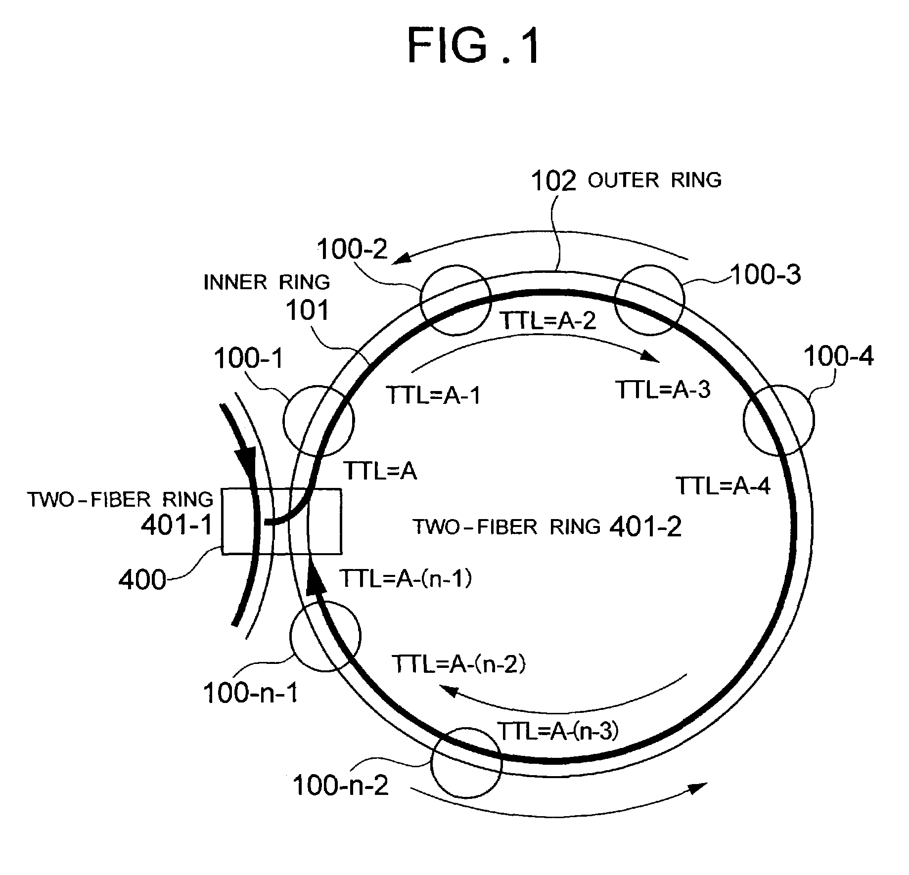
[0058]FIG. 1 shows a multiring configuration in which two-fiber rings 401-1 and 401-2 each formed of ring nodes 100 are bridged by a ring node 400. In the two-fiber ring 401-2, a total of n number of ring nodes 100 and 400 are connected.

[0059]The ring node 400 is given in advance the addresses of the ring nodes 100 and 400 and the total number n on the two-fiber rings 401-2 bridged by it. Description will be made by assuming that a ring frame transmitted in an inner ring 101 and an outer ring 102 between the ring nodes 100 and 400 is the same as the ring frame 180 shown in FIG. 13. However, it is not necessarily required that the ring frame transmitted through these rings have the same configuration as the ring frame 180, and the ring frame in this embodiment may have at least t...

embodiment 2

[0066]A ring node configuration for inter-ring bridging for realization of the first method for efficient discard of a ring frame will be described with reference to FIG. 3.

[0067]FIG. 3 shows the configuration of the ring node 400 bridging the two-fiber rings 401-1 and 401-2 shown in FIG. 1.

[0068]The configuration of the ring node 400 is symmetrical about a ring bridge 650. In FIG. 1, functional blocks corresponding to each other in the symmetrical configuration are indicated by symbols such as x-1 and x-2 (x: functional block number). For ease of description, indication with “-1” and “-2” is omitted in the following description.

[0069]The ring node 400 is constituted by multiplexing circuits 130 and 131, protection switches 150, TTL comparators 610 and 611, pass / drop determination circuits 620 and 621, TTL setting circuits 630 and 631, ring protection processing / topology management circuits 640, and the ring bridge 650. The inner ring 101-1 and the outer ring 102-1 belong to the sam...

third embodiment

[0081]A method for protection from an inter-ring bridge node fault in accordance with the present invention will be described with reference to FIGS. 4 to 6 and also to the flowchart of FIG. 13 showing the operation of the third embodiment. It is assumed that a faulty-end wrap protection method based on the conventional art is used as an in-ring protection method.

[0082]FIGS. 4 to 6 show a multiring configuration in which two-fiber rings 701-1 to 701-3 each formed by ring nodes 700 are bridged by ring nodes 710.

[0083]In each of the two-fiber rings 701-1 to 701-3, each of the ring nodes 700 and 710 belonging to the two-fiber ring monitors the fault condition of its junction links. In the event of a fault, the ring node notifies the other ring nodes 700 and 710 belonging to the same two-fiber ring 701-1, 701-2, or 701-3 of fault information. The ring nodes 710-1, 710-2, and 710-3 for inter-ring bridging belong to one protection domain 704. If a fault occurs at one of the ring nodes 710...


PUM


Abstract

The invention enables protection of a ring frame transferred via an inter-ring bridge ring node when a fault occurs at the node in a multiring. Ring nodes form a ring protection domain to enable one ring node to be bypassed by using other ring nodes when a fault occurs at this ring node. The TTL value of ring frame to be transferred through the bypass is set to a value obtained by adding the number of hops h to the faulty ring node to a common initial value A in the same two-fiber ring to enable detection of a characteristic TTL value at a bypassing ring node. The bypass fur the ring frame is selected with reference to the characteristic TTL value at the bypassing ring node.

Description

BACKGROUND OF THE INVENTION[0001]1. Field of the Invention[0002]The present invention relates to a multiring control method, a node using the method, and a control program. More particularly, the present invention relates to a method of discarding a ring frame in a multiring and a protection method.[0003]2. Description of the Prior Art[0004]With the increase in traffic of data typified by Internet protocols (IP), a demand for efficient data transmission has arisen even on conventional communication service companies which have mainly offered voice transmission service (hereinafter referred to as “carrier”). Also in the field of data transmission networks, there is a demand for a highly reliable protection method such as one conformable to “SONET, GR-1230-Core, Issue 3 Dec. 1996 Bellcore” on which conventional transmission networks are based. Spatial Reuse Protocol (hereinafter referred to as SRP) (RFC 2892 IETF) can be mentioned as a highly reliable protection method for data transm...

Claims


Application Information

Patent Timeline
IPC IPC(8): H04J1/16H04J3/14H04J3/08H04L12/437H04L12/46
CPCH04J3/085H04L12/437H04L12/462
Inventor TAKAGI, KAZUOUMAYABASHI, MASAKI
Owner NEC CORP
Why Eureka
Try Eureka