Optical connector with total internal reflection abutting surface

a technology of optical connectors and abutting surfaces, applied in the field of optical connectors, can solve the problems of not being able to disclose, and achieve the effect of frustration of total internal reflection

Active Publication Date: 2008-01-29
HUBERSUHNER POLATIS LTD
View PDF19 Cites 2 Cited by
  • Summary
  • Abstract
  • Description
  • Claims
  • Application Information

AI Technical Summary

Benefits of technology

[0011]This configuration is particularly advantageous because it allows the upgrading of an existing optical line with absolutely minimal disruption to traffic. It simplifies network planning by allowing later upgrades with optical add-drop multiplexer (OADM) filters, etc, again with minimal impact on existing traffic. It reduces capital expenditure by enabling a pay-as-you-grow policy to be followed. It decreases operational expenditure by simplifying the upgrading process. It improves network performance by eliminating unnecessary components and by allowing in-service upgrades with amplifiers and DSCM s(dispersion compensation modules), etc.
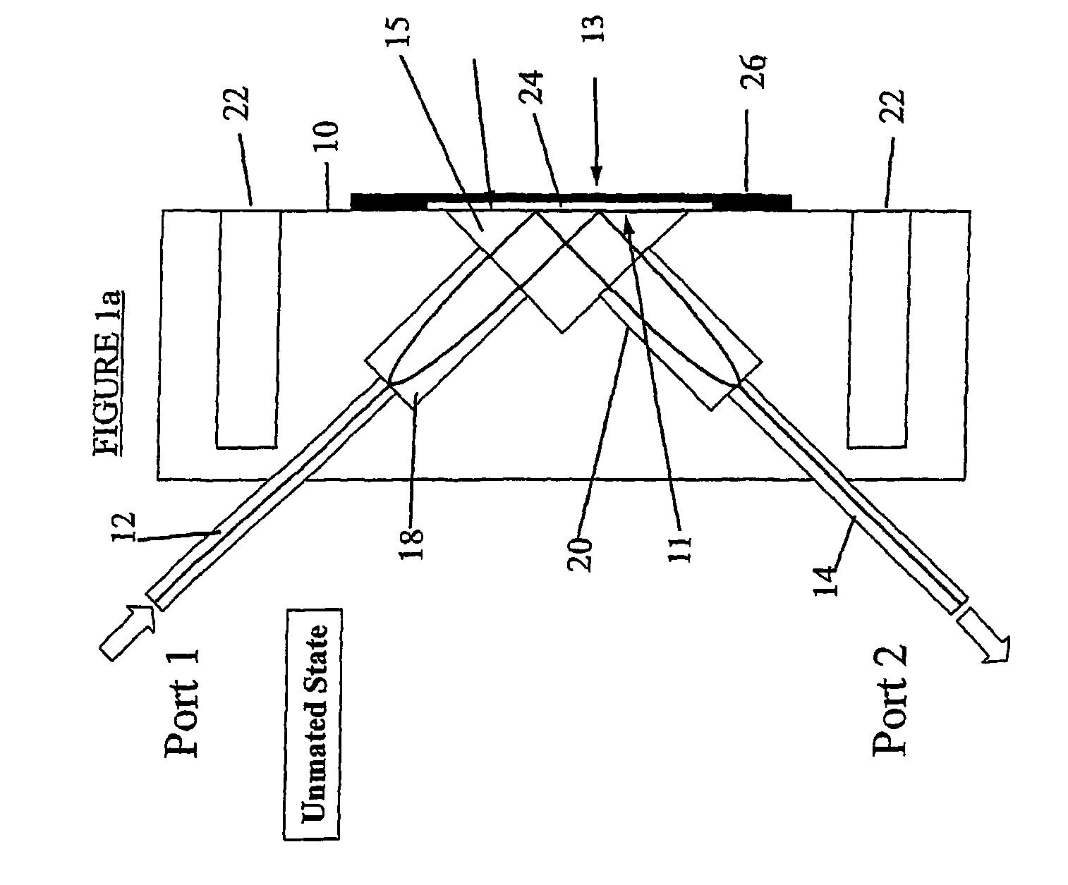
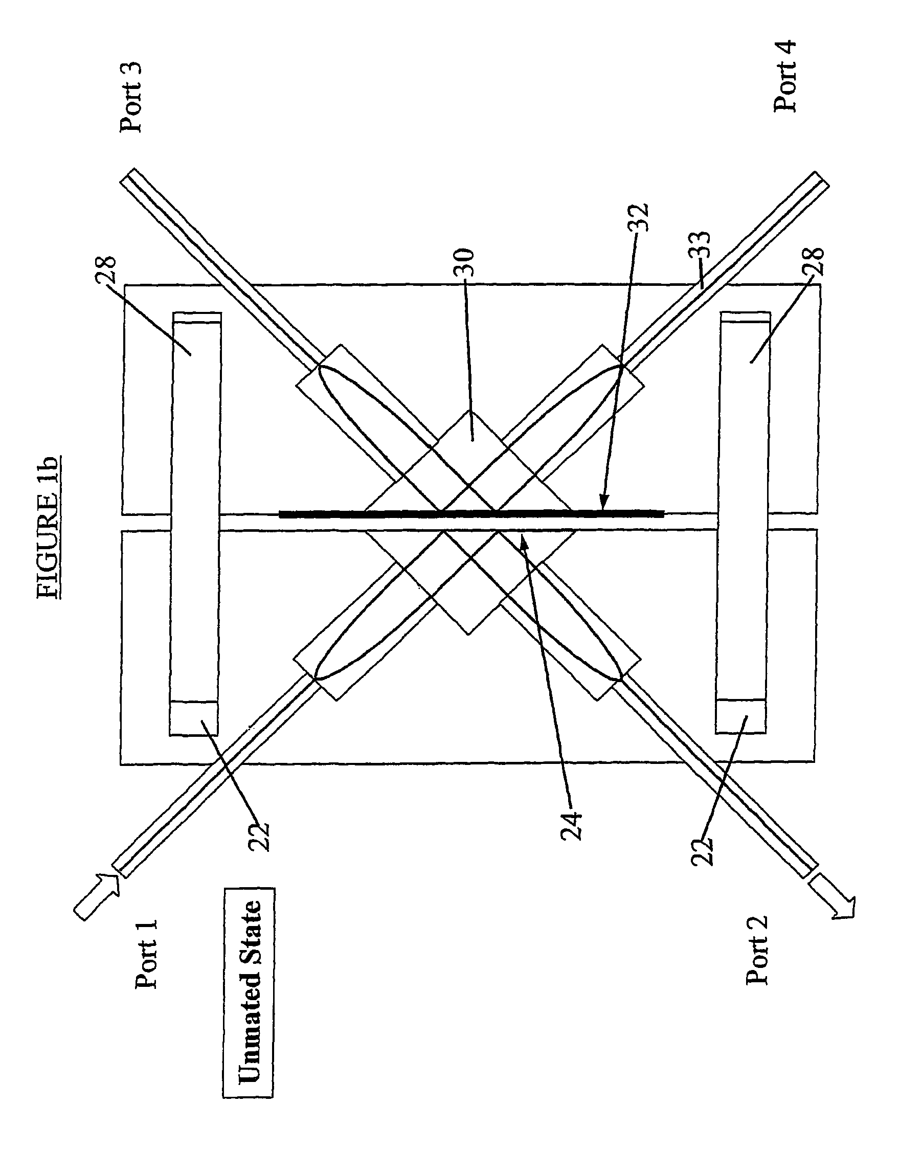
[0013]In a further subsidiary aspect, the connector comprises means enabling the connector to interlock with any other optical connector which is appropriately matingly configured and which incorporates means which will frustrate the total internal reflection of the first said connector if and when the connector were to be interlocked with any such other connector; and with the interlock-enabling means of the connector being so operatively positioned that, with the connector interlocked to another suitable connector as aforesaid, the total internal reflection surface of the connector will be in sufficient proximity to the total internal reflection frustrating means of the other connector as to allow the optical radiations to pass across the connection then formed by the two interlocking connectors.
[0014]In a subsidiary aspect in accordance with the invention's broadest aspect, said optical element towards which radiation is reflected in said first mode treats the radiation so that eye-damaging radiation remains within the connector, thereby advantageously the connector may achieve an eye-safe operation.
[0016]In a further subsidiary aspect, the interlocking means allow a mating connector to be first attached in non-surface frustrating manner and then incorporates a mechanism which provides a snap-action final closure for the frustration of the surface.
[0017]In a further subsidiary aspect, additional reflection means are provided between the optical guides and the surface. This advantageous configuration may for example allow optical guides to be parallel within the connector and even normal to the total internal reflection surface.

Problems solved by technology

Whilst some of these disclose devices with a total internal reflection surface, none of these discloses the following aspects.

Method used


Image

  • Optical connector with total internal reflection abutting surface
  • Optical connector with total internal reflection abutting surface
  • Optical connector with total internal reflection abutting surface

Examples


third embodiment

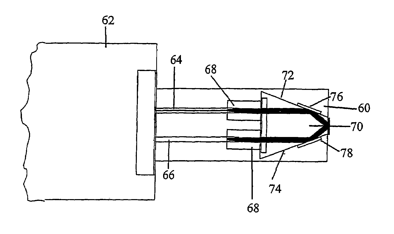
[0058]the optical connector according to the invention is illustrated in FIG. 5. This shows a curved refractive element 82 (a hemispherical ball lens), which performs the same reflective functions as the element shown in FIGS. 2 and 3, but in addition uses its curved surface to perform the collimation and focussing operations.

fourth embodiment

[0059]In a fourth embodiment, shown in FIG. 6, a ferrule 86 incorporates a Graded Index (GRIN) Lens 84 employed to perform both the focussing and beam deflection functions for radiation from fibre 85. This is preferably a high aperture GRIN, with a numerical aperture of approximately 0.6, with, for example an index of 1.468 at the radius where the fibre cores are attached (SMF28 fibre), thereby minimising back reflection, and an index of 1.85 at the centre, giving a beam incidence angle of ˜35 degrees to the normal. This comfortably exceeds the critical angle of 32 degrees between the high index material and air.

[0060]The Grin lens is ¼ of a pitch long (hence will translate position at the fibers to angle at the centre of the mating surface). With the fibres as close together as possible, which is advantageous as it reduces the angular alignment tolerance of the connector ferrules), a typical length of the lens of around 0.2 mm, with a diameter at the fibre cores of around 125 mm, a...

fifth embodiment

[0061]FIG. 7 shows a fifth embodiment incorporating a ball lens 87 with a polished planar total internal reflection surface 88 at the glass-air interface. The lens is set to perform the deflection and collimation functions by refraction at the curved interface. A space 89 is provided between the optical guides and the ball lens which may be filled with air, a vacuum or any other appropriate low index fluid.


PUM


Abstract

An optical connector (10) comprises at least one optical guide (12) for carrying optical radiations; a total internal reflection surface (11) upon which, in use, said radiations impinge, so that the radiation in the optical guide is reflected by said surface towards an optical element (14) of the connector and means enabling the connector (10) to interlock with any other optical connector which is appropriately matingly configured.

Description

FIELD OF THE INVENTION [0001]The invention relates to optical connectors. The optical connectors in question may be used in a wide variety of application for example optical connector arrangements for use in a fibre-optic communications system, optical network sections. They may also be used for example in improved methods to increase the functionality of an optical network.BACKGROUND TO THE INVENTION [0002]One of the major problems in designing optical networks is in the placement of the optical components on the network. Design decisions on the inclusion and placement of components need to accommodate not only the initial traffic on the network, but also future network growth, which is often unpredictable. This issue is especially critical for Metropolitan (or city) networks where cost needs to be minimised and growth is especially unpredictable.[0003]The normal approach to the problem is to include enough elements initially to accommodate currently foreseen traffic growth, and to...

Claims


Application Information

Patent Timeline
Patent Type & Authority Patents(United States)
IPC IPC(8): G02B6/26G02B6/42G02B6/32G02B6/35G02B6/36G02B6/38
CPCG02B6/325G02B6/3506G02B6/3825G02B6/3878G02B6/3522G02B6/3546G02B6/3574G02B6/3846G02B2006/4297
Inventor DAMES, ANDREW NICHOLASLEWIS, DAVIDPARSONS, NICHOLASGRANT, MICHAELHOLDSWORTH, ADRIAN
Owner HUBERSUHNER POLATIS LTD
Why Eureka
Try Eureka