
Gem setting

a technology of gemstones and stones, applied in the field of gemstone or synthetic stone setting, can solve the problems of time-consuming and expensive conventional gem setting for inside bezel setting, and achieve the effects of reducing costs, reducing breakage, and saving labor and tim

Inactive Publication Date: 2008-02-05
BERNSEN ROGER M
View PDF4 Cites 1 Cited by
  • Summary
  • Abstract
  • Description
  • Claims
  • Application Information

AI Technical Summary

Benefits of technology

[0005]The present invention is an improved setting for either gem or synthetic stones, round, oval or pear-shaped either faceted or cabochon utilizing the aesthetic and inherently protective (shielding) properties associated with the classic inside bezel mounting. The invention, self-centering setting provides for the stone to be permanently set with minimum risk to the stone during the actual setting process. Additional advantages associated with the present invention are the considerable labor and time savings, resulting in reduced costs, reduced breakage and more importantly providing a cost effective method to obtain the predictable angle and contiguous finish on the inside bezel face. This action can be accomplished by finishing and polishing the bezel face pre-stone setting which previously was an impossible task due to the nature of the top down inside bezel setting techniques. The major aesthetic advantage of pre-establishing this bezel angle face is that this angle can be precisely calculated thus maximized for the refracted light out or the reflected light in through the crown of the stone using the present invention.
[0012]Furthermore, present “inside bezel” settings require exceptionally fine detailed workmanship by those highly skilled in the art, hence labor costs are very prohibitive in a production environment. Secondarily “prong” style mountings are inexpensive to produce but ultimately leave the consumer with problems of durability, and potential loss of investment. The present invention is an improved method for setting stones which is attractive, durable and easy to implement.
[0013]While several types of settings exist, none securely fixes a gem within a setting while maximizing the visible area of external reflection with the adjunct concentric bezel face thus enhancing the results of internal refraction too. Also, none is as easy to install as the present invention.

Problems solved by technology

The conventional gem setting for an inside bezel setting is expensive and time consuming due to the difficult task of trying to maximize the refractive light out or in to the crown of the stone.

Method used


Image

  • Gem setting
  • Gem setting
  • Gem setting

Examples


Embodiment Construction

[0034]The present invention is an improved setting for a gem. The invention is also a method for placing a gem in a setting.

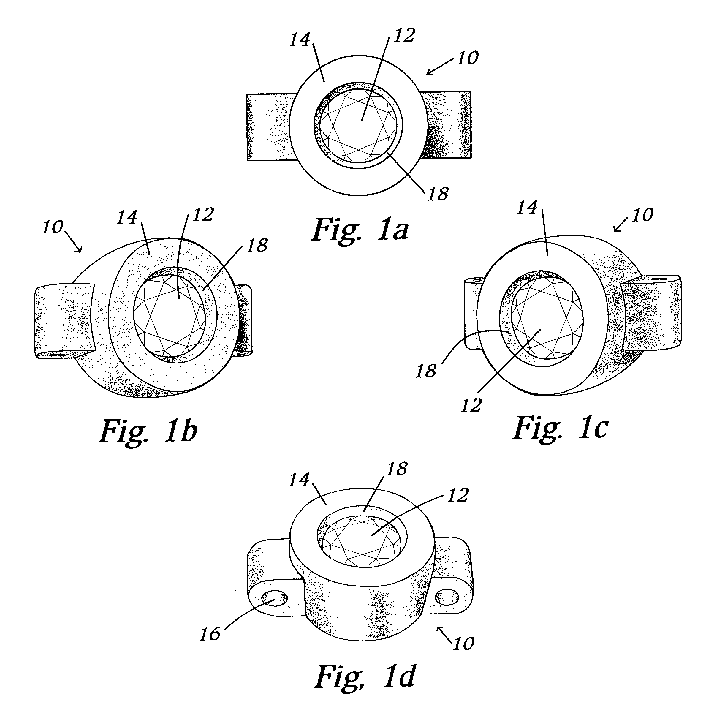
[0035]The invention is shown as 10 in FIGS. 1a-1d. The invention is shown as used, securing a gem 12. The setting 14 surrounds the enclosed gem 12. The setting can be used for a ring; however, the setting 14 may have voids 16 or other structure for fastening the setting 14 to a bracelet (not shown), so that the setting 14 may be used for a pendant, bracelet, earring, or other form of jewelry. The setting 14 has a bezel 18 which secures the gem from coming out of the top of the setting 14. As shown, the bezel 18 is located around the circumference of the inside void in the setting 14. However, the bezel may alternatively be only a portion of the circumference.

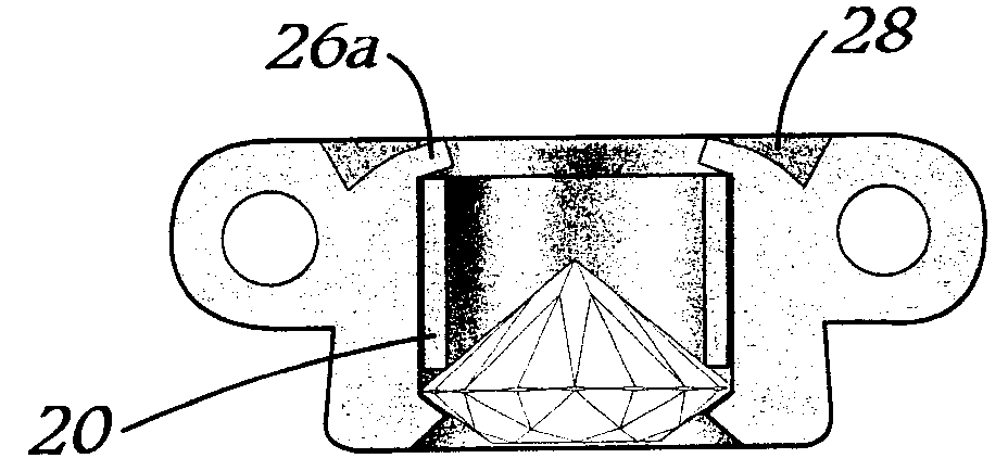
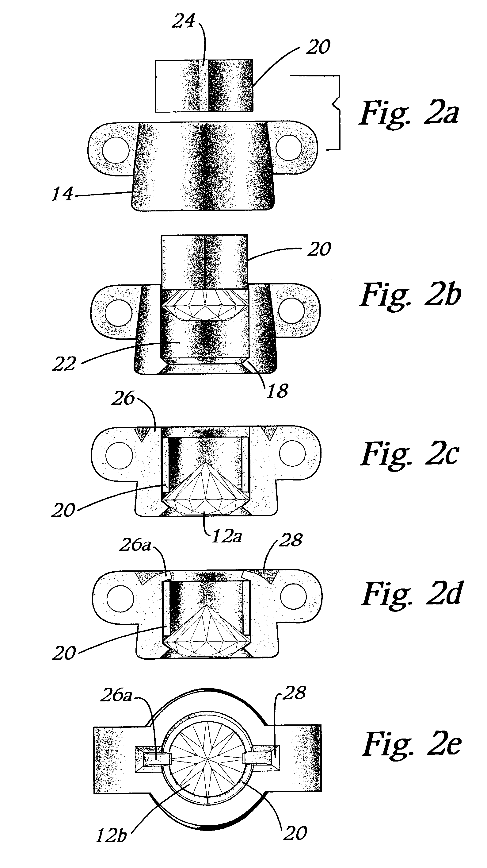
[0036]FIGS. 2a-2e illustrate the inventive process for securing a gem within a setting. A circular spring 20 is used to secure the gem 12 within a cavity 22 in the setting 14. As shown, the spring 20 is gen...


PUM


Abstract

A method and stone mount for an inside bezel mounting that improves precisely calculating the bezel face angle and contiguous finish on the inside bezel face for enhanced light brilliance that includes mounting the stone from the bottom up using a retaining spring. The stone once inserted into the mounting stops at the bezel lip then the retaining spring once fully inserted can be permanently affixed by bending the countersunk prongs over said retaining spring thus completing the setting.

Description

BACKGROUND OF INVENTION[0001]1. Field of the Invention[0002]This invention relates to an improved gem or synthetic stone setting for an inside bezel mounting that results in considerable time and cost savings in order to provide a precisely calculated bezel angle face and contiguous finish on the inside bezel face for enhanced light brilliance.[0003]2. Description of Related Art[0004]In the world of setting stones, either gem stones or synthetic stones, for an inside bezel setting, conventionally the stones were mounted from the top down. The conventional gem setting for an inside bezel setting is expensive and time consuming due to the difficult task of trying to maximize the refractive light out or in to the crown of the stone. The present invention dramatically improves the setting for either gem or synthetic stones (regardless of their shapes) for the inside bezel mounting. The present invention provides a major aesthetic advantage of pre-establishing the bezel angle face which ...

Claims


Application Information

Patent Timeline
Patent Type & Authority Patents(United States)
IPC IPC(8): A44C17/02
CPCA44C11/007
Inventor BERNSEN, ROGER M.
Owner BERNSEN ROGER M
Learn More