
Uterine artery occlusion device with cervical receptacle

a uterine artery and occlusion device technology, applied in the field of treating uterine disorders of female patients, can solve the problems of many undesirable characteristics, attendant risks of patients' bodies, and many physicians' inability to possess the training or equipment necessary to perform catheter-based uterine artery embolization, so as to improve the treatment of uterine disorders, the effect of reducing the risk of catheterization

Inactive Publication Date: 2008-02-05
VASCULAR CONTROL SYST
View PDF130 Cites 33 Cited by
  • Summary
  • Abstract
  • Description
  • Claims
  • Application Information

AI Technical Summary

Benefits of technology

[0017]The non-invasive devices and systems embodying features of the invention allow for the non-surgical location and occlusion of uterine arteries without the puncture of bodily tissue, and without the need for radiographic equipment or for skill in the use of radiographic techniques. The devices and methods are simpler and more readily used and removed than other methods and devices, and provide improved treatments for uterine disorders that might otherwise require invasive and irreversible treatments such as removal of a hysterectomy.

Problems solved by technology

However, a hysterectomy is a major surgical intrusion into a patient's body having attendant risks and many undesirable characteristics.
However, many physicians do not possess the training or equipment necessary to perform catheter-based uterine artery embolization under radiologic direction.

Method used


Image

  • Uterine artery occlusion device with cervical receptacle
  • Uterine artery occlusion device with cervical receptacle
  • Uterine artery occlusion device with cervical receptacle

Examples


Embodiment Construction

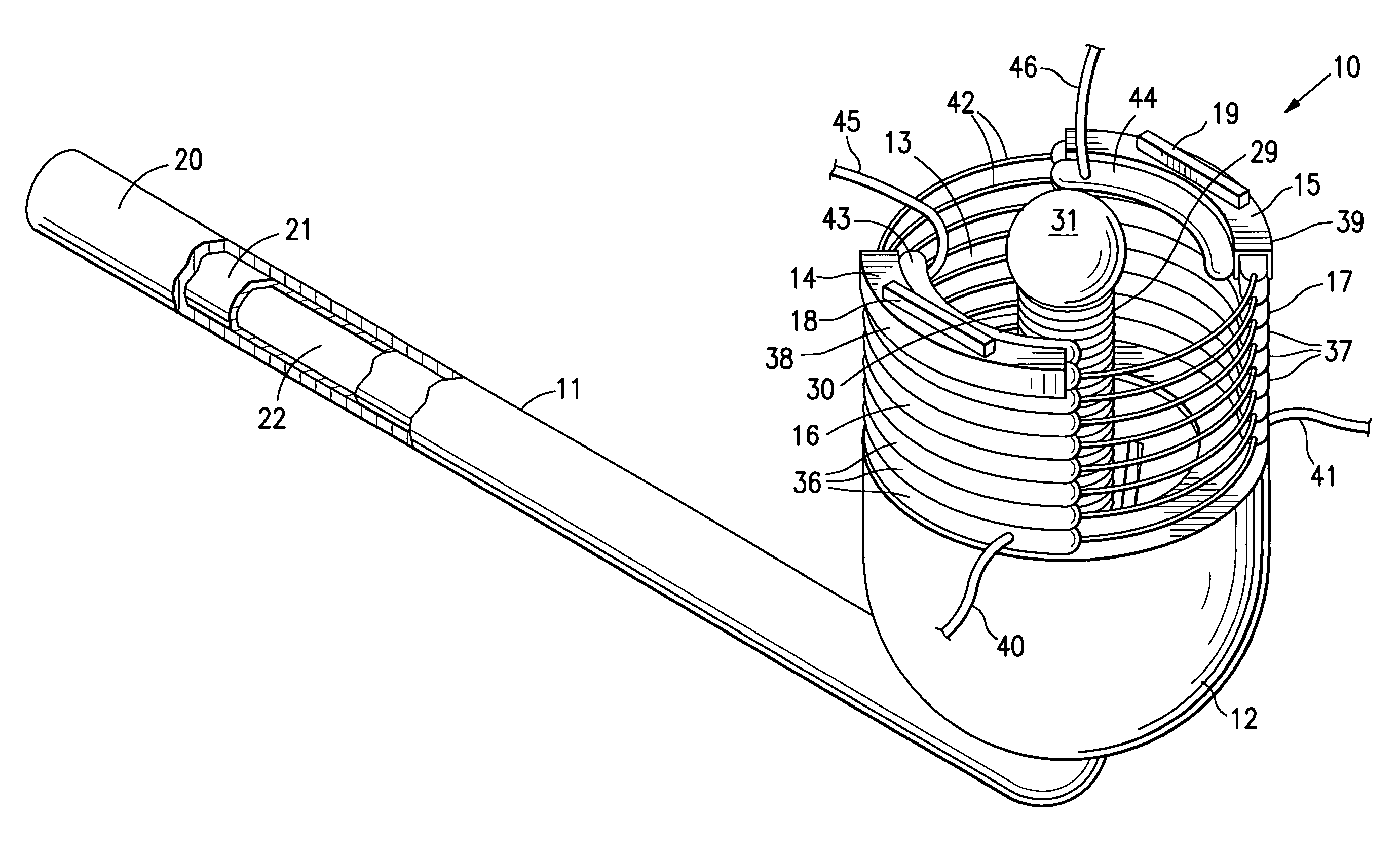
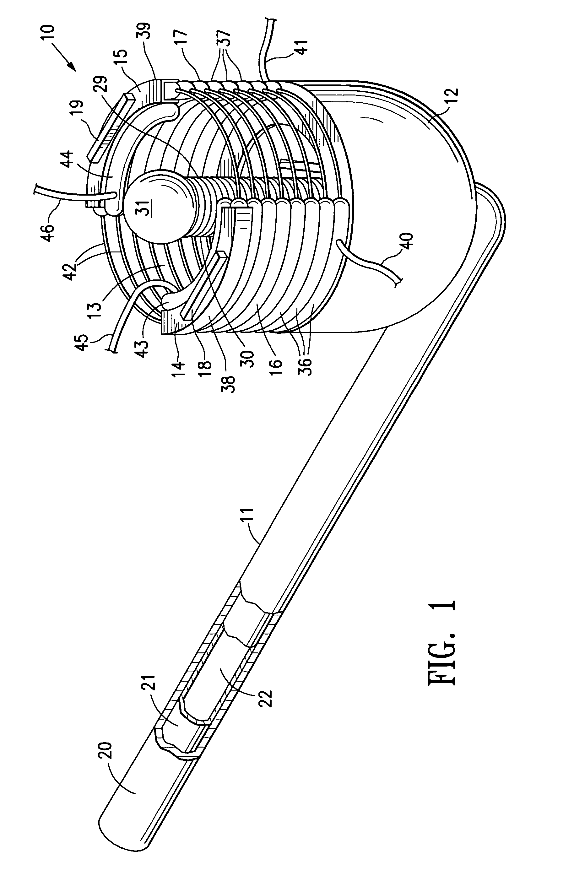
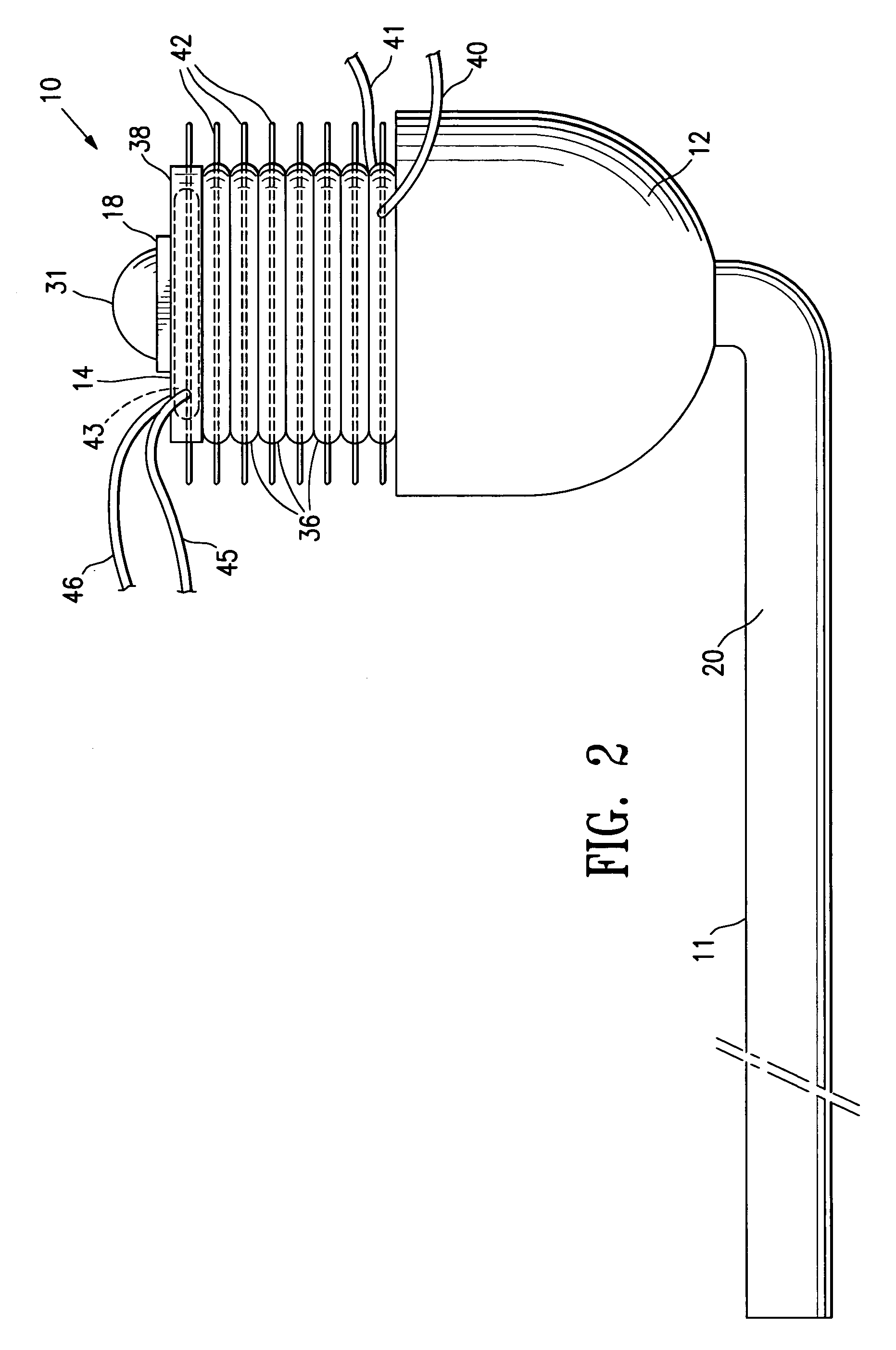
[0034]FIGS. 1-5 show an intravaginal uterine artery occluding device 10 embodying features of the invention. The device 10 includes an elongated shaft or handle 11 and a cervical receptacle 12 on the distal end of the shaft which has an interior chamber 13 configured to receive at least part of the patient's uterine cervix and which has leading edges 14 and 15 for applying pressure to the patient's vaginal fornix adjacent the uterine cervix to occlude underlying or adjacent uterine arteries. Distally extendable curtains 16 and 17 are secured at their proximal ends to the open distal end of receptacle 12 and leading edges 14 and 15 are secured to the distal ends of curtains 16 and 17 respectively. Blood flow sensors 18 and 19 are provided on the leading edges 14 and 15 to aid in the location of the patient's uterine arteries.

[0035]The elongated shaft 11 is formed of outer and inner tubular members 20 and 21 respectively and has an inner lumen 22 extending within the inner tubular mem...


PUM


Abstract

An intravaginal uterine artery occlusion device is used for treating uterine disorders such as fibroids, dysfunctional uterine bleeding, postpartum hemorrhage and the like. A occlusion device has a cervical receptacle with an open distal end for receiving the patients uterine cervix, an elongated shaft having a distal end secured to the closed proximal end of the cervical receptacle, and an inner lumen extending to the distal end of the shaft. The patient's uterine cervix is held within the interior of the receptacle by the application of a vacuum to the interior of the receptacle through the inner lumen of the shaft while the leading edge(s) of the cervical receptacle press against the patient's vaginal fornix to occlude the uterine artery. A blood flow sensor may be provided on the leading edge of the receptacle to aid in locating a uterine artery and to monitor blood flow through the uterine artery.

Description

FIELD OF THE INVENTION[0001]The invention relates generally to the field of treating uterine disorders of female patients by occluding the patient's uterine arteries.BACKGROUND OF THE INVENTION[0002]Hysterectomy (surgical removal of the uterus) is performed on approximately 600,000 women annually in the United States. Hysterectomy is often the therapeutic choice for the treatment of uterine cancer, adenomyosis, menorrhagia, prolapse, dysfunctional uterine bleeding, and muscular tumors of the uterus, known as leimyoma or uterine fibroids.[0003]However, a hysterectomy is a major surgical intrusion into a patient's body having attendant risks and many undesirable characteristics. Thus, any method which can provide the therapeutic result of a hysterectomy without removing the uterus would be a significant improvement in this field. Newer treatment methods have been developed for some uterine disorders to avoid removal of the patient's uterus.[0004]For example, in 1995, it was demonstrat...

Claims


Application Information

Patent Timeline
Patent Type & Authority Patents(United States)
IPC IPC(8): A61B17/08A61B17/42A61F6/06A61F6/14A61B5/026A61B8/06A61B17/12
CPCA61B5/026A61B5/489A61B5/6834A61B8/06A61B17/12A61B17/42A61B2017/4216
Inventor BURBANK, FRED H.JONES, MICHAEL L.ALTIERI, GREIG E.ELIZONDO-RIOJAS, GUILLERMO
Owner VASCULAR CONTROL SYST
Learn More