Intraocular pressure control

a technology of intraocular pressure and control, which is applied in the field of microsurgical systems, can solve the problems of not being able to maintain an optimal intraocular pressure during ophthalmic surgery, affecting and reducing the effect of intraocular pressure from the dead head pressur

Active Publication Date: 2008-02-05
ALCON INC
View PDF69 Cites 55 Cited by
  • Summary
  • Abstract
  • Description
  • Claims
  • Application Information

AI Technical Summary

Benefits of technology

[0006]In another aspect of the present invention, an infusion chamber is provided. The infusion chamber has a first chamber for holding irrigating fluid and a second chamber for holding irrigating fluid. The first chamber is not fluidly coupled to the second chamber. An irrigating fluid is provided from an infusion source to the first chamber and the second chamber. The irrigating fluid is provided to a surgical device from the first chamber during a microsurgical procedure, and this step is ended when the level of the irrigating fluid in the first chamber reaches a bottom limit. Upon such ending, the irrigating fluid is provided to the surgical device from the second chamber, and the first chamber is refilled with the irrigating fluid from the infusion source.

Problems solved by technology

Maintaining an optimum intraocular pressure during ophthalmic surgery is currently problematic.
However, when aspiration is applied, the intraocular pressure drops dramatically from the dead head pressure due to all the pressure losses in the aspiration circuit associated with aspiration flow.
Clinically, such over-pressurizing of the eye is not ideal.

Method used


Image

  • Intraocular pressure control
  • Intraocular pressure control
  • Intraocular pressure control

Examples


Embodiment Construction

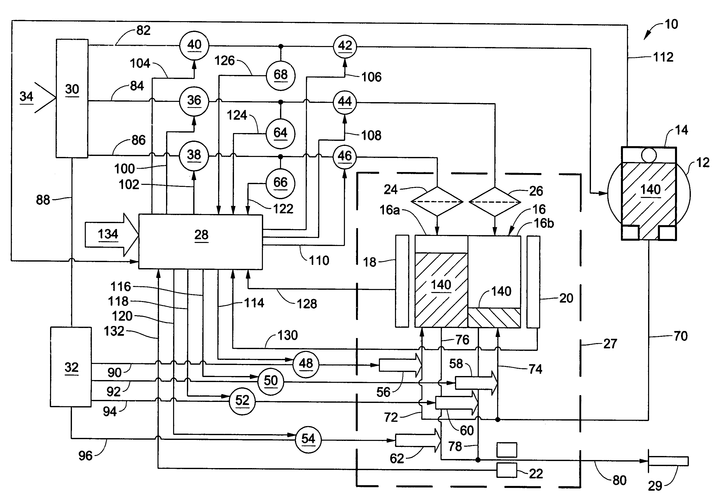
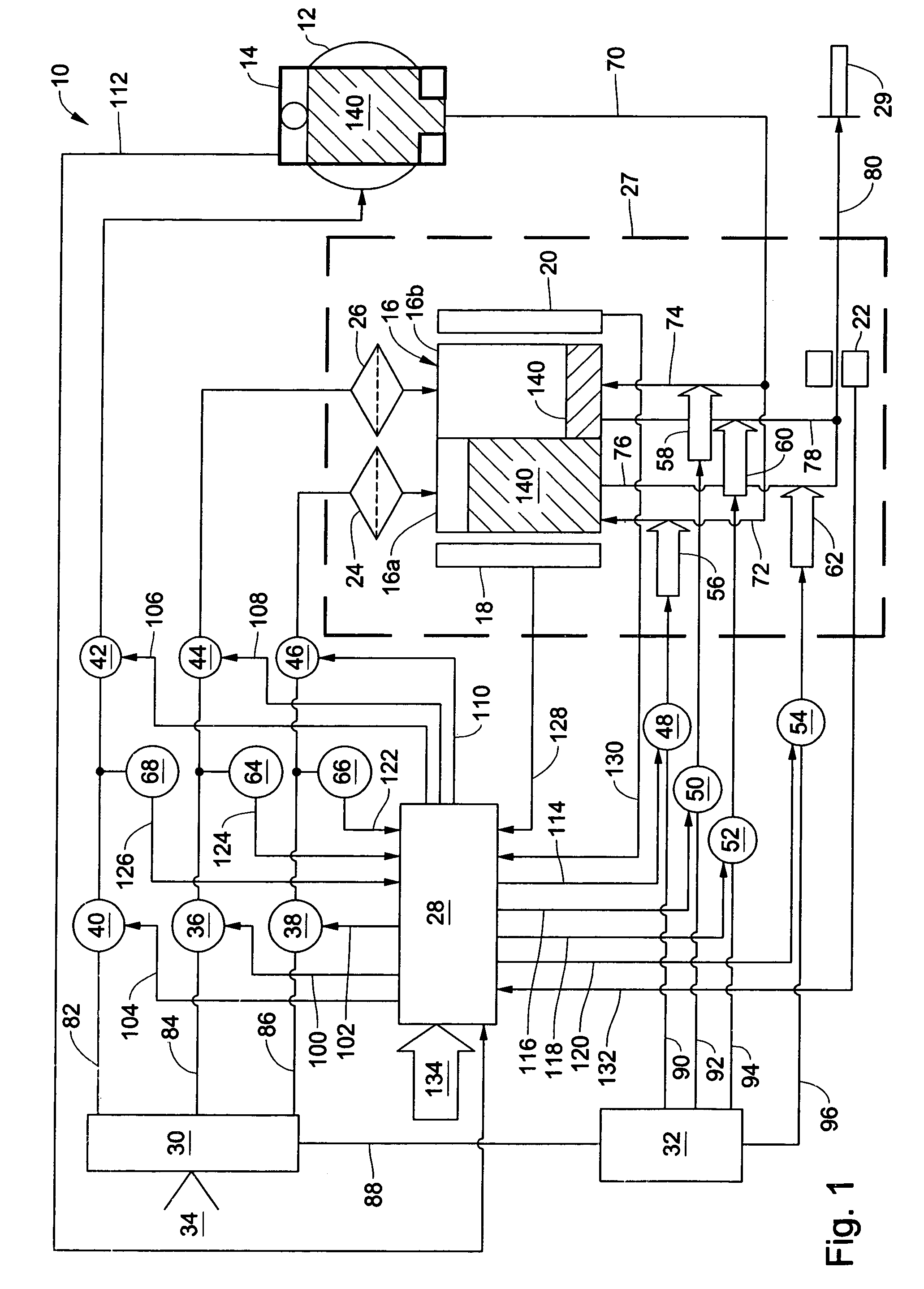
[0010]The preferred embodiments of the present invention and their advantages are best understood by referring to FIGS. 1-2 of the drawings, like numerals being used for like and corresponding parts of the various drawings. As shown in FIG. 1, ophthalmic microsurgical system 10 includes a pressure cuff 12; an infusion source 14; a dual infusion chamber 16 having a chamber 16a and a chamber 16b; fluid level sensors 18 and 20; a flow sensor 22; filters 24 and 26; a surgical device 29; a computer or microprocessor 28; gas manifolds 30 and 32; a pressurized gas source 34; proportional solenoid valves 36, 38, and 40; “on / off” solenoid valves 42, 44, 46, 48, 50, 52, 54; actuators 56, 58, 60, and 62; and pressure transducers 64, 66, and 68. Dual infusion chamber 16; fluid level sensors 18 and 20; portions of infusion fluid lines 70, 72, 74, 76, 78, and 80; and portions of gas lines 84 and 86 are preferably disposed in a surgical cassette 27. Infusion source 14; dual infusion chamber 16; fl...


PUM


Abstract

An improved method of controlling intraocular pressure with a microsurgical system using measured flow rate and a dual infusion chamber.

Description

FIELD OF THE INVENTION[0001]The present invention generally pertains to microsurgical systems and more particularly to controlling intraocular pressure in ophthalmic surgery.DESCRIPTION OF THE RELATED ART[0002]During small incision surgery, and particularly during ophthalmic surgery, small probes are inserted into the operative site to cut, remove, or otherwise manipulate tissue. During these surgical procedures, fluid is typically infused into the eye, and the infusion fluid and tissue are aspirated from the surgical site.[0003]Maintaining an optimum intraocular pressure during ophthalmic surgery is currently problematic. When no aspiration is occurring, the pressure in the eye becomes the pressure of the fluid being infused into the eye. This pressure is typically referred to as the “dead head pressure”. However, when aspiration is applied, the intraocular pressure drops dramatically from the dead head pressure due to all the pressure losses in the aspiration circuit associated wi...

Claims


Application Information

Patent Timeline
Patent Type & Authority Patents(United States)
IPC IPC(8): A61M1/00A61M5/00A61M31/00
CPCA61M3/0233A61M3/0216A61F9/007A61M2205/3331A61M2205/3389A61M3/0254A61M3/0202
Inventor NAZARIFAR, NADERREED, FREDERICKHUCULAK, JOHN C.THOMAS, ROGER
Owner ALCON INC
Why Eureka
Try Eureka