Floor heating system

a floor heating and heating element technology, applied in the field of floor heating systems, can solve the problems of large number of resistive wires to be inventoried, lot of thermal energy drawn off, etc., and achieve the effect of reducing the number of different resistivity wires and easy butt splicing

Active Publication Date: 2008-02-05
ETI INC
View PDF11 Cites 4 Cited by
  • Summary
  • Abstract
  • Description
  • Claims
  • Application Information

AI Technical Summary

Benefits of technology

[0009]An advantage of the present invention is that the heating system reduces the number of different resistivity wires that must be stocked to meet the power density required for heating a range of floor areas.
[0010]Another advantage of the present invention is that the segments can be easily butt spliced together.

Problems solved by technology

The problem with this system is that a lot of thermal energy is drawn off by way of the fuel feeding hole and the chimney when a fire is not kindled therein.
A problem with this approach is that a significant number of resistive wires must be inventoried to meet a range of floor areas.

Method used


Image

  • Floor heating system
  • Floor heating system
  • Floor heating system

Examples


Embodiment Construction

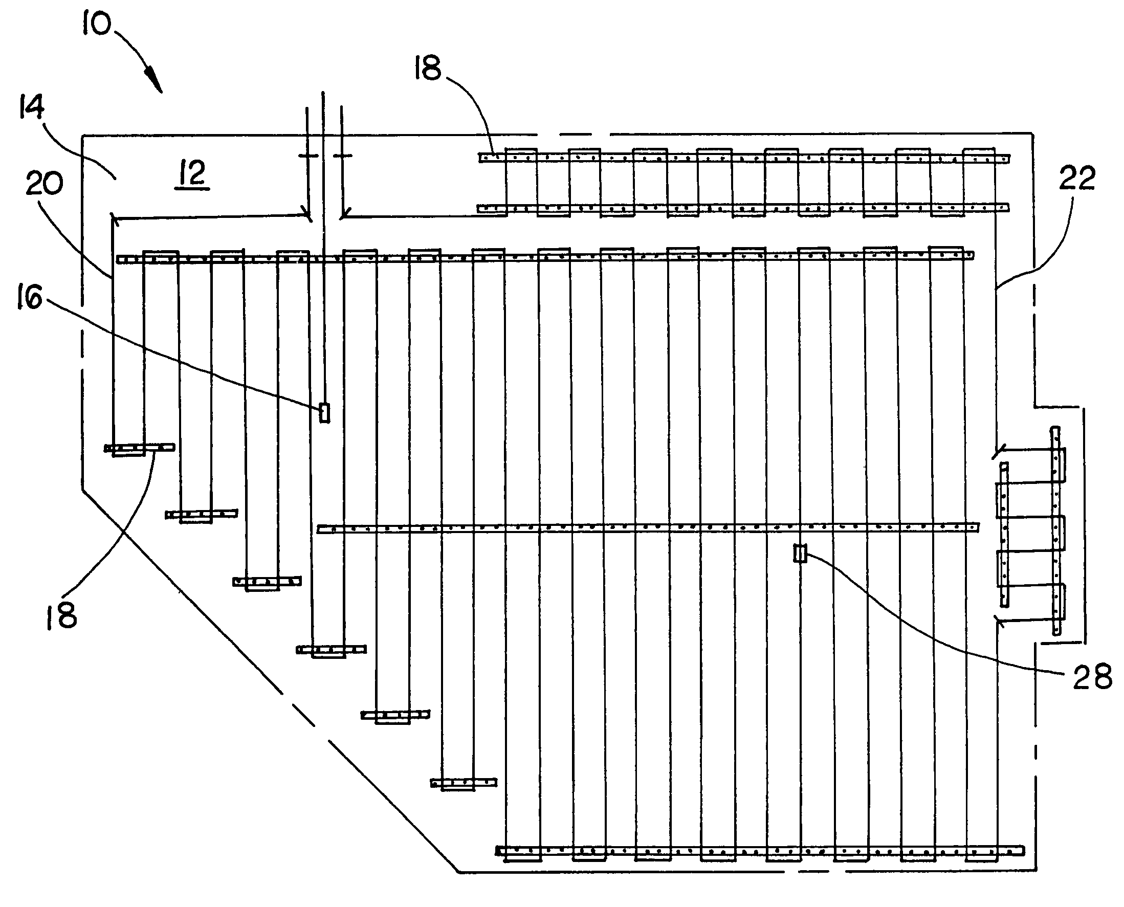
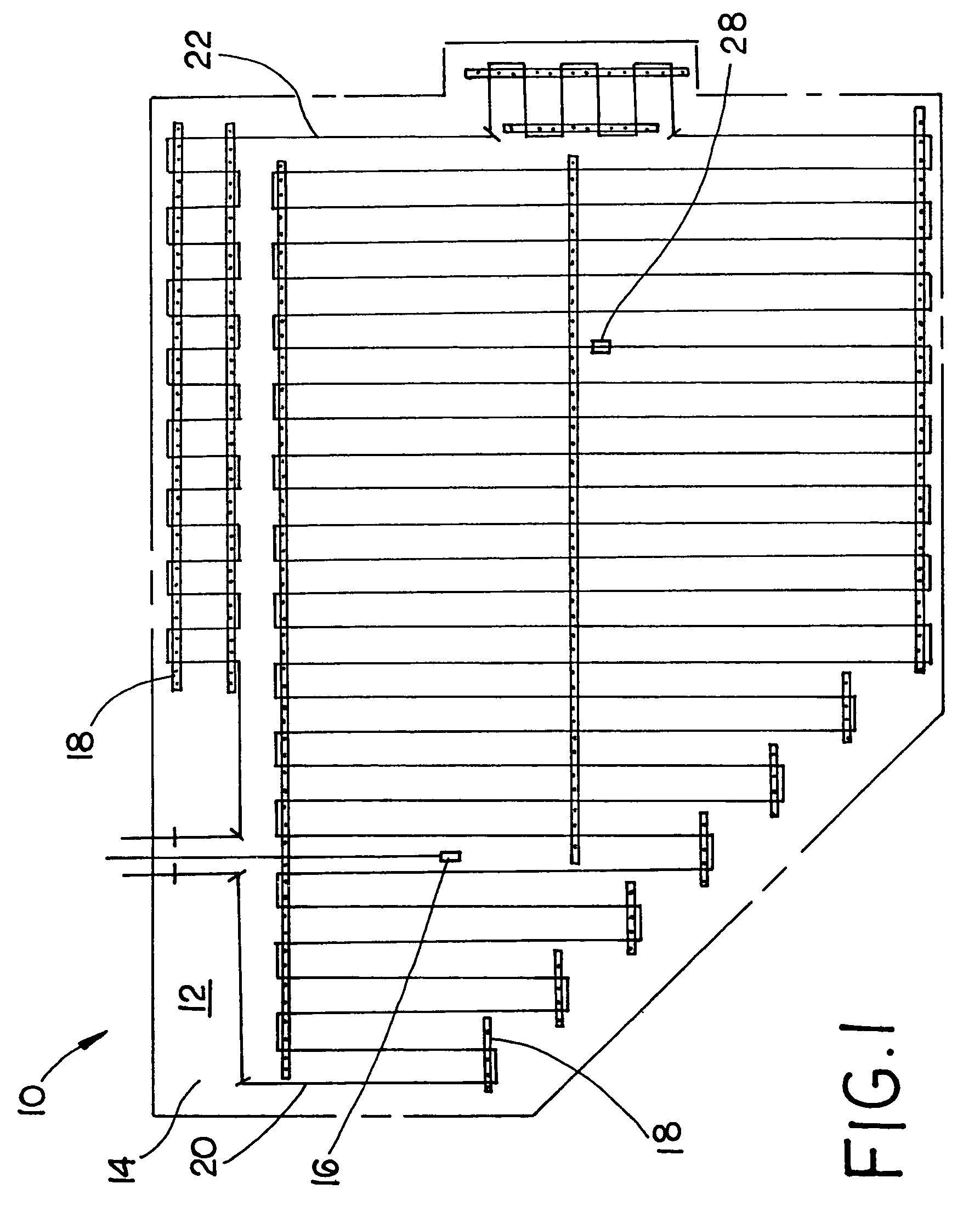
[0019]Referring now to the drawings, and more particularly to FIG. 1, there is shown a floor heating system 10 installed upon a floor 12. Floor 12 has a surface area 14, which is utilized in the calculation of the resistivity of the heating conductors as well as the lengths of the heating conductors. Floor heating system 10 includes a temperature sensor 16, fasteners 18, a first resistive conductor assembly 20 and a second resistive conductor assembly 22. Floor 12 is a base floor, also known as a sub-floor 12, which may underlie a finished floor in an area in which a heated floor such as a ceramic floor is desirable. Onto floor 12 there is attached fasteners 18, which may be in the form of clips 18 to which first resistive conductor assembly and second resistive conductor assembly 22 is attached. The use of two resistive conductor assemblies in this illustration is illustrative of the current method and more than two resistive conductor assemblies may be utilized in this invention. ...


PUM


Abstract

A floor heating system including a sub-floor, a plurality of fasteners, a first heater conductor assembly and a second heater conductor assembly. The first conductor assembly including a first resistive conductor having a first length, first and second ends, and two low resistance conductors. The two low resistance conductors being respectively connected to each of the first and second ends. The second heater conductor assembly including a second resistive conductor having a second length, first and second ends, and two low resistance conductors. The two low resistance conductors being respectively connected to each of the first and second ends of the second resistive conductor. The low resistance conductor that is connected to the first end of the first resistive conductor being connected in a serial fashion to the low resistance conductor that is connected to the first end of the second resistive conductor. The first length being approximately a first integer multiple of the second length. The first resistive conductor and the second resistive conductor having substantially the same resistivity per unit of length. The plurality of fasteners connecting the first heater conductor assembly and the second heater conductor assembly to the sub-floor.

Description

BACKGROUND OF THE INVENTION[0001]1. Field of the Invention[0002]The present invention relates to a floor heating system, and, more particularly, to an electrical floor heating system.[0003]2. Description of the Related Art[0004]Under floor heating systems date back thousands of years including Roman and Korean heating system where stone slabs are installed on an upper part of flues in a hypocaust connected with a fuel feeding port and a chimney. A burning fuel, such as wood or coal is burnt thereby heating the floor from the underneath side. The problem with this system is that a lot of thermal energy is drawn off by way of the fuel feeding hole and the chimney when a fire is not kindled therein. Some modern floor heating systems include the circulation of a heated thermal medium fluid through long, thin seamless pipes disposed beneath a floor. A floor heating system that involves the circulation of a thermal medium fluid has a portion of a floor that is heated to a higher temperatu...

Claims


Application Information

Patent Timeline
Patent Type & Authority Patents(United States)
IPC IPC(8): H05B3/00
CPCF24D13/02H05B6/56Y02B30/26Y02B30/00
Inventor JONES, THADDEUS M.
Owner ETI INC
Why Eureka
Try Eureka