Optical pickup and optical information recording apparatus using the same

a technology of optical information and recording equipment, applied in the direction of data recording, instruments, disposition/mounting of heads, etc., can solve the problems of inconvenient use of in-line dpp method, difficulty in detecting satisfactory tracking error signals by conventional dpp method, and inability to meet the requirements of the type of disk to be used, etc., to achieve the effect of improving versatility and reliability

Active Publication Date: 2008-02-05
HITACHI MEDIA ELECTORONICS CO LTD +1
View PDF9 Cites 14 Cited by
  • Summary
  • Abstract
  • Description
  • Claims
  • Application Information

AI Technical Summary

Benefits of technology

[0023]It is therefore the object of the present invention to provide a new tracking error signal detection unit capable of resolving the main problem with the in-line DPP method having deterioration of properties of the tracking error signal accompanying the object lens displacement, while maintaining the aforementioned advantages of the in-line DPP method, that is, capable of consistently detecting a practical tracking error signal from which tracking offsets has been satisfactorily removed from various types of optical disks having different track pitches, being less affected by the difference in the disk track pitch and the object lens displacement in the tracking direction. The present invention especially aims to realize a tracking error signal detection unit with improved versatility and reliability, and to provide an optical pickup and an optical information recording / reproducing apparatus employing such a tracking error signal detection unit.

Problems solved by technology

However, the conventional DPP method explained above also involves the following problem in practical use.
In the conventional DPP method, however, if the irradiation positioned interval δ of the three convergence spots is adjusted and optimized for the tracking error signal detection from DVD-RAM, the irradiation positioned interval δ then become almost equal to the track pitch of DVD-R and DVD-RW, by which the tracking error signal detection from DVD-R and DVD-RW by the conventional DPP method becomes difficult.
In short, if a single optical pickup is employed for various types of optical disks having different track pitches, the detection of satisfactory tracking error signals by the conventional DPP method might become difficult or impossible for some types of disks.
However, the in-line DPP method still involves a major problem in practical use as described below.
Thus, in order to obtain a usable tracking error signal by the conventional in-line DPP method, the object lens displacement has to be limited to an extremely narrow permissible range, by which practical performance of the optical pickup is necessitated to be impaired seriously at present.

Method used


Image

  • Optical pickup and optical information recording apparatus using the same
  • Optical pickup and optical information recording apparatus using the same
  • Optical pickup and optical information recording apparatus using the same

Examples


Embodiment Construction

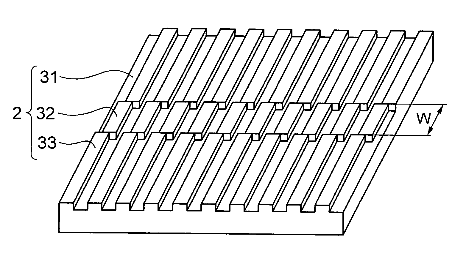
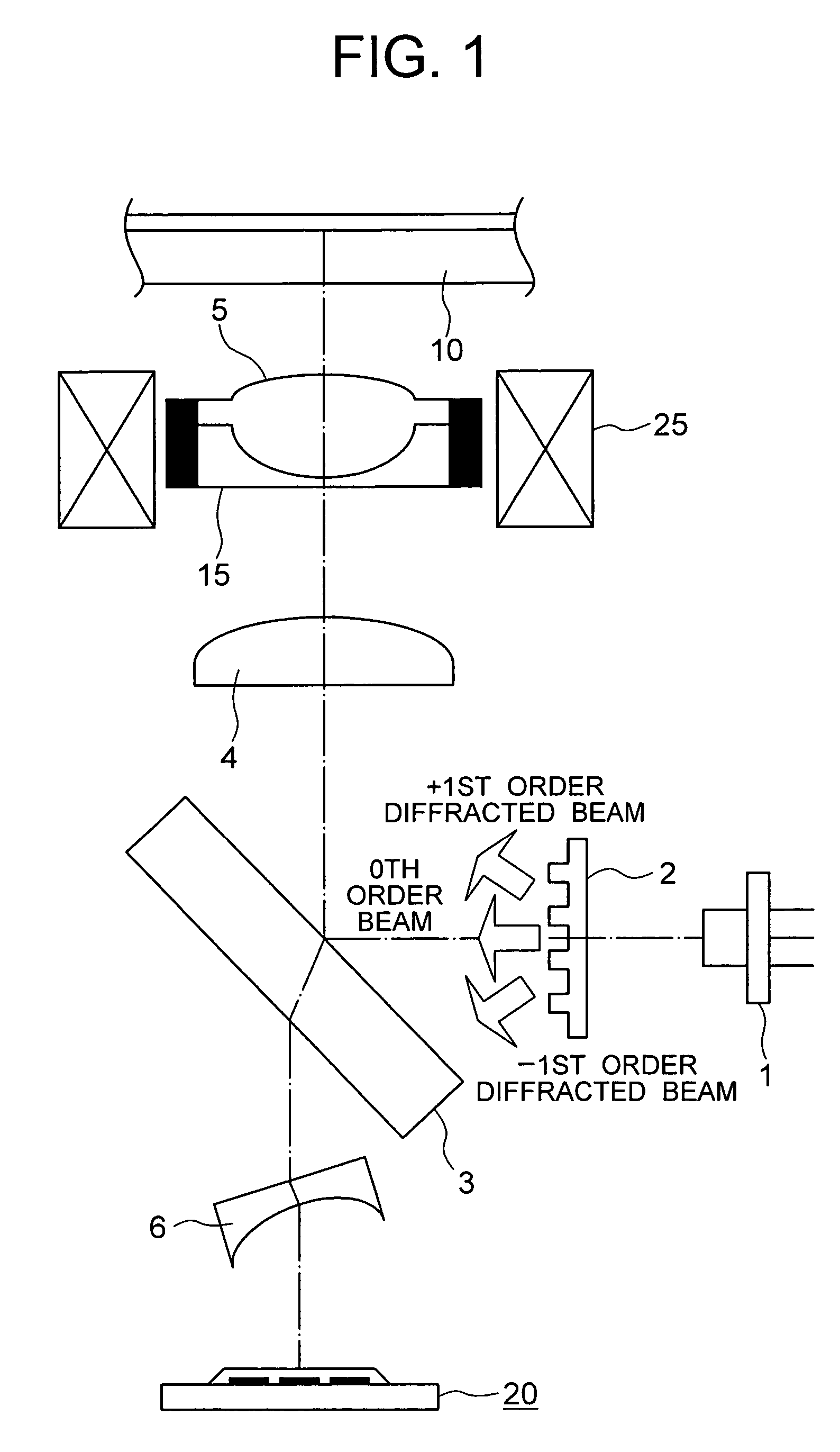
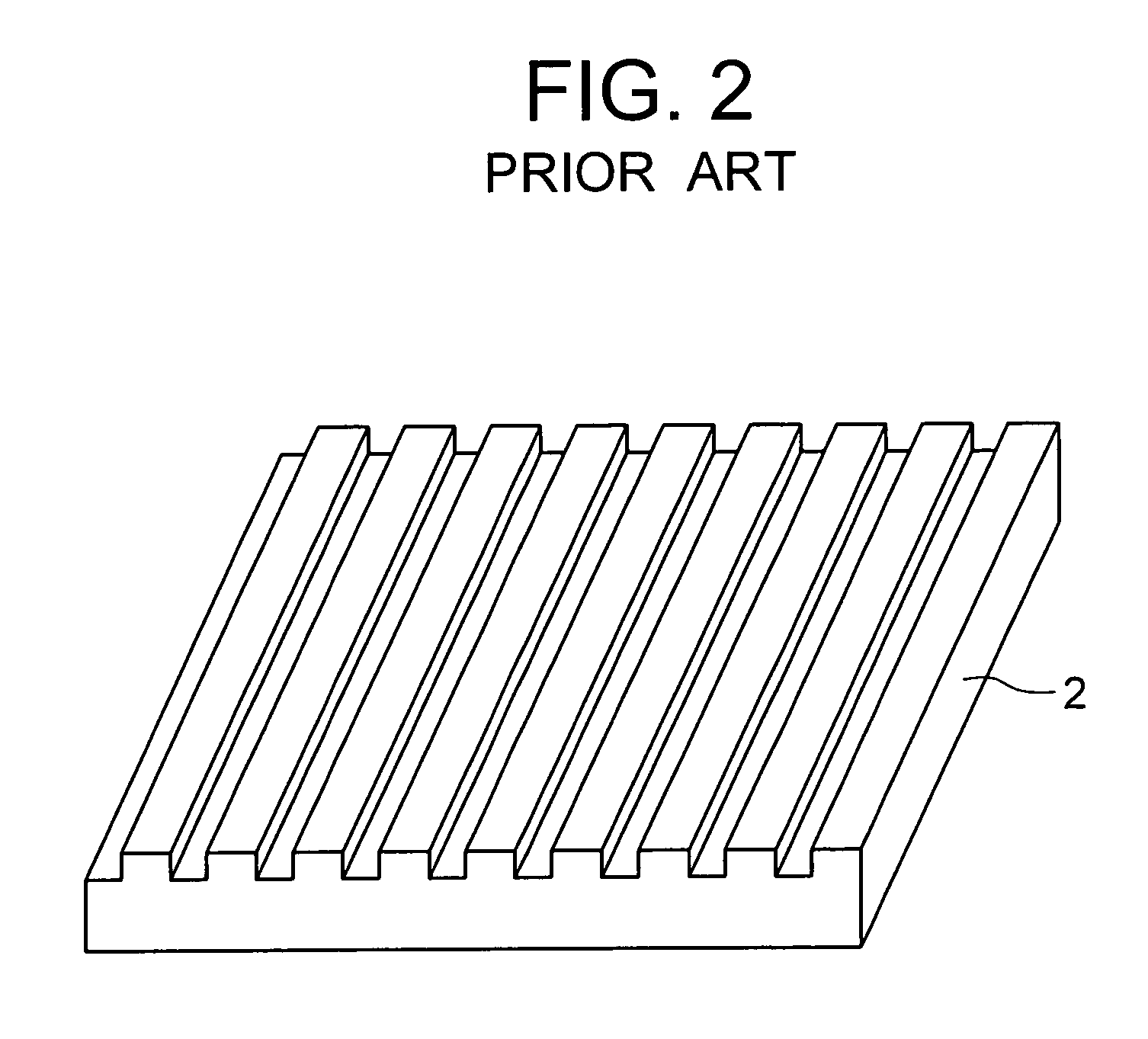
[0050]Referring now to the drawings, a description will be given in detail of embodiments in accordance with the present invention. While FIG. 1, schematically showing elements of the present invention, has already been used for the description of the prior art, it will be used again for the explanation of the following embodiments. In the following description, elements which have already been explained using reference numerals will be referred to the same reference numerals.

[0051]FIG. 1 is a schematic block diagram showing an example of an optical pickup in accordance with the present invention, in which the reference numeral 1 denotes a semiconductor laser light source, 3 denotes a half mirror or beam splitter, 4 denotes a collimator lens, 5 denotes an object lens, 6 denotes a detection lens, 10 denotes an optical disk, and 20 denotes a photodetector having photoreceptor surfaces partitioned according to a prescribed pattern. The object lens 5, being fixed in a lens holder 15, is...


PUM

PropertyMeasurementUnit
widthaaaaaaaaaa
widthaaaaaaaaaa
widthaaaaaaaaaa

Abstract

An optical pickup includes a diffraction grating partitioned into three areas, in which the phase of periodic grating groove structure in an area is successively shifted from that in the adjacent area by 90°. In the generation of a differential push-pull signal, an amplification factor K for sub push-pull signals is varied depending on the type of the optical disk. By such composition of the optical pickup, amplitude deterioration of the tracking error signal accompanying displacement of the object lens is reduced.

Description

BACKGROUND OF THE INVENTION[0001]1. Field of the Invention[0002]The present invention relates to an optical pickup having the function of recording information signals on an optical information record medium (hereafter, simply referred to as “optical disk”) or reproducing information which has been recorded on an optical disk by irradiating a spot beam on a recording surface of the optical disk, and an optical information recording / reproducing apparatus equipped with the optical pickup.[0003]2. Prior Art[0004]Optical pickups are generally configured to detect a focus error signal and a tracking error signal, and control the position of an object lens with use of the error signals so that a converged beam spot (hereafter, also referred to as a “convergence spot”) can be placed correctly on a proper recording track of an optical disk. As typical methods for detecting the tracking error signal, a 3-spot method, a push-pull method, a differential push-pull method (hereafter, referred to...

Claims


Application Information

Patent Timeline
Patent Type & Authority Patents(United States)
IPC IPC(8): G11B7/00G11B7/09G11B7/135
CPCG11B7/0903G11B7/0945G11B7/1353G11B2007/0006
Inventor OHNISHI, KUNIKAZUKAWAMURA, TOMOTOINOUE, MASAYUKI
Owner HITACHI MEDIA ELECTORONICS CO LTD
Why Eureka
Try Eureka