Method and system for registering 3D models of anatomical regions with projection images of the same

a technology of anatomical regions and projection images, applied in the field of medical imaging systems, can solve the problems of high incidence of complications in patients with af, cumbersome and lengthy current approaches to mapping and ablation using current fluoroscopically guided techniques

Active Publication Date: 2008-02-05
APN HEALTH +1
View PDF71 Cites 165 Cited by
  • Summary
  • Abstract
  • Description
  • Claims
  • Application Information

AI Technical Summary

Problems solved by technology

Patients with AF tend to have a high incidence of such complications as stroke and congestive heart failure.
The three-dimensional reconstruction of the left atrium using some currently available technologies, the inability of the physician to visualize the pulmonary vein ostia (opening of these veins into the left atrium) from inside, the varying size of the pulmonary veins and thus the pulmonary vein ostia, the difficulty in keeping the mapping and ablation catheters stable at the pulmonary vein ostial site due to the complex 3D geometry of these areas, all make current approaches to mapping and ablation using current fluoroscopically guided techniques somewhat cumbersome and lengthy.
A factor that may be associated with the above mentioned limitation is that the operator typically guides an interventional tool using mainly the fluoroscopy images.
Despite considerable progress in the management of congestive heart failure (CHF), it remains a major health problem worldwide.
Despite significant advances in the treatment of CHF using various pharmacological therapies, quality-of-life in patients with CHF is poor as they are frequently hospitalized, and heart failure is a common cause of death.
In addition, there is significant cost attached to this problem.
There are, however, several problems with this approach.
First, this type of procedure is time-consuming.
Second, placement of the LV lead is limited to sites available that provide reasonable pacing and sensing parameters.
And third, cannulating the coronary sinus may be challenging as a result of an enlarged right atrium, rotation of the heart, or presence of Tebesian valve (a valve close to the opening of the coronary sinus).
Coronary sinus stenosis (occlusion) has also been reported in patients with prior coronary artery bypass surgery, further complicating the problem.
In most instances, problems with the placement of the coronary sinus lead are identified at the time of the interventional procedure.
Unfortunately, there are many problems with epicardial lead placement as well, some of which include but are not limited to:
Potential risk of damaging the coronary arteries and venous system; and
Difficulty in identifying the ideal pacing site as a result of one or more of the above limitations.
However, due to the unstable nature of the coronary sinus lead, a pacing and sensing lead is usually placed in the right ventricle in currently used techniques.
The presence of scarring from previous heart attacks may make this uncoordinated contraction even worse.
While existing medical procedures may be suitable and appropriate for certain medical conditions, procedural limitations still exist.

Method used


Image

  • Method and system for registering 3D models of anatomical regions with projection images of the same
  • Method and system for registering 3D models of anatomical regions with projection images of the same
  • Method and system for registering 3D models of anatomical regions with projection images of the same

Examples


first embodiment

[0059]In a first embodiment, the apparent diameter of the catheter 260 in the fluoroscopy image 182 is determined and then compared with the known actual diameter of the catheter 260. From this information, the actual dimension of an anatomical structure in the anatomical region 255 in the fluoroscopy image 182 may be determined. The anatomical structure in the fluoroscopy image 182 is then matched with the same anatomical structure in the 3D model 184, where now the actual and apparent sizes of the same anatomical structure in the 3D model 184 may be compared. From this comparison, a scaling factor may be established between the first and second image acquisition systems 115, 118.

second embodiment

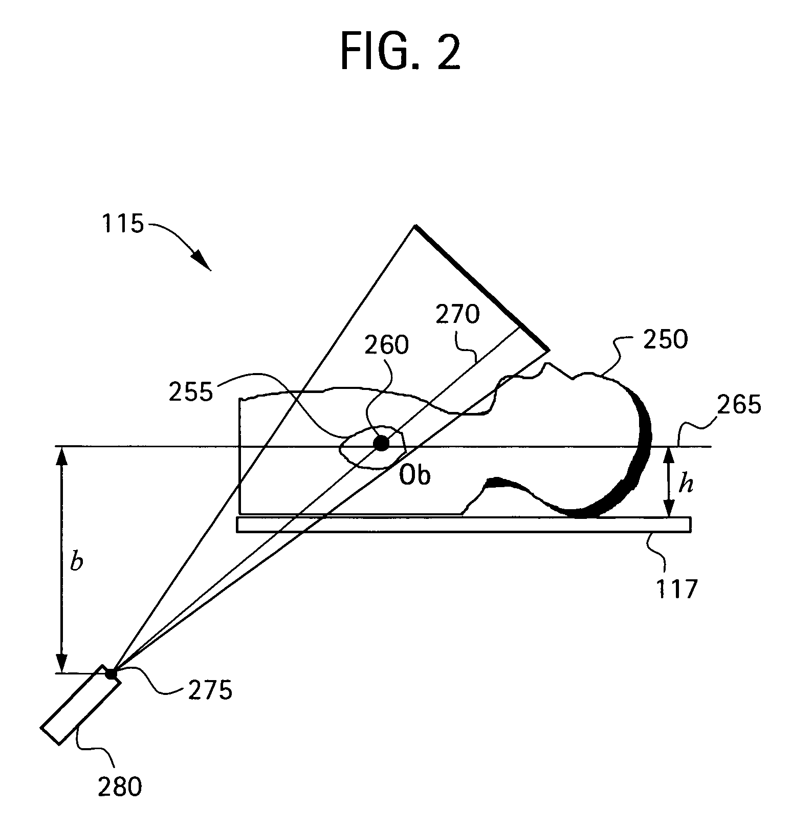
[0060]In a second embodiment, the catheter 260 is disposed at a known anatomical structure in the anatomical region 255 at a location defined by the intersection of a horizontal plane 265 and the line 270 joining the focal point 275 of the fluoroscopy system 115 to the projection of the catheter 260 in the fluoroscopy image 182. Here, the horizontal plane 265 is defined by an elevation h above the anatomical reference system 117 to the known anatomical structure in the fluoroscopy system 115, which establishes a known location of the catheter 260 in the fluoroscopy system 115 and the CT system 118 relative to the anatomical reference system 117. Knowing the location of the catheter 260 in the 3D model 184 and the actual and apparent dimensions for elevation h in the 3D model 184, the actual size of the same anatomical structure in the 3D model 184 as that in the fluoroscopy image 182 may be determined. By comparing the actual and apparent sizes of the anatomical structure in the 3D ...

third embodiment

[0061]In a third embodiment, the fluoroscopy system 115 is used to produce a first and a second set of fluoroscopy projection images, which are generated using at least two different x-ray projections separated by an angle sufficient to produce discernibly different projection images of the anatomical region 255. Here, as in other embodiments, the catheter 260 is disposed at a known anatomical structure in the anatomical region 255. By analyzing the two sets of projection images using a known triangulation approach, the location of the catheter 260 in the 3D model 184 with respect to the focal point 275 of the x-ray source 280 of the fluoroscopy system 115 may be determined, thereby defining a dimension b, which establishes a known location of the catheter 260 in the fluoroscopy system 115 and the CT system 118 relative to the focal point 275. Knowing the location of the catheter 260 in the 3D model 184 and the actual and apparent dimensions for dimension b in the 3D model 184, the ...


PUM


Abstract

An imaging system for use in a medical intervention procedure is disclosed. A first image acquisition system of a first modality employing a catheter at an anatomical region of a patient is configured to produce a first image of the anatomical region using fluoroscopy, the first image comprising a set of fluoroscopy projection images. A second image acquisition system of a second different modality is configured to generate a 3D model of the anatomical region. An anatomical reference system is common to both the first and second image acquisition systems. A processing circuit is configured to process executable instructions for registering the 3D model with the fluoroscopy image in response to the common reference system and discernible parameters associated with the catheter in both the first and second image acquisition systems.

Description

BACKGROUND[0001]This invention relates generally to a medical imaging system, and more particularly to a method and apparatus for registering 3D models of anatomical regions with projection images of the same.[0002]During a number of interventional procedures related to the improvement of electrical therapy in the heart, the physician has to manipulate catheters and / or leads inside the heart chambers. An example of the two most complex and common procedures include atrial fibrillation (AF) ablation, and bi-ventricular pacing.[0003]Atrial fibrillation, an arrhythmia in which the atria (upper chambers of the heart) stop contracting as they fibrillate, is the most common of the heart rhythm problems. In United States alone it is estimated that there are over 2 million people who have atrial fibrillation. Present data suggest that it is the most common arrhythmia-related cause of hospital admissions. Patients with AF tend to have a high incidence of such complications as stroke and cong...

Claims


Application Information

Patent Timeline
Patent Type & Authority Patents(United States)
IPC IPC(8): G06K9/00G06K9/32A61B6/00G06F19/00
CPCA61B6/032A61B6/12A61B6/466A61B6/503A61B6/5235A61B19/52G06T5/50A61B5/7289A61B6/5247A61B6/5288A61B6/541A61B19/50A61B34/10A61B90/36
Inventor VAILLANT, REGISSRA, JASBIR SINGHCOUSTY, JEANKOTIAN, FRANCOIS
Owner APN HEALTH
Why Eureka
Try Eureka