Stent having helical elements

a technology of helical elements and stents, applied in the field of prosthetic stents, can solve the problems of limited flexibility and difficult delivery and placement in narrow vessels

Inactive Publication Date: 2008-02-12
ORBUSNEICH MEDICAL PTE LTD
View PDF27 Cites 176 Cited by
  • Summary
  • Abstract
  • Description
  • Claims
  • Application Information

AI Technical Summary

Benefits of technology

[0009]In one embodiment of the present invention, the stent may comprise a first non-helical endzone and a second non-helical endzone that straddle the main body. The main body is generally cylindrically shaped and has a cylindrical axis. A plurality of adjacent main body cylindrical elements are connected together to form the main body of the stent. Each main body cylindrical element may be comprised of a plurality of expandable first and second circumferential elements. In some embodiments, the second circumferential elements have a circumferential dimension less than the circumferential dimension of the first circumferen

Problems solved by technology

These include, but are not limited to: (i) low stent-to-vessel ratio uniformity, (ii) comparative rigidity of the stent in a

Method used


Image

  • Stent having helical elements
  • Stent having helical elements
  • Stent having helical elements

Examples


Embodiment Construction

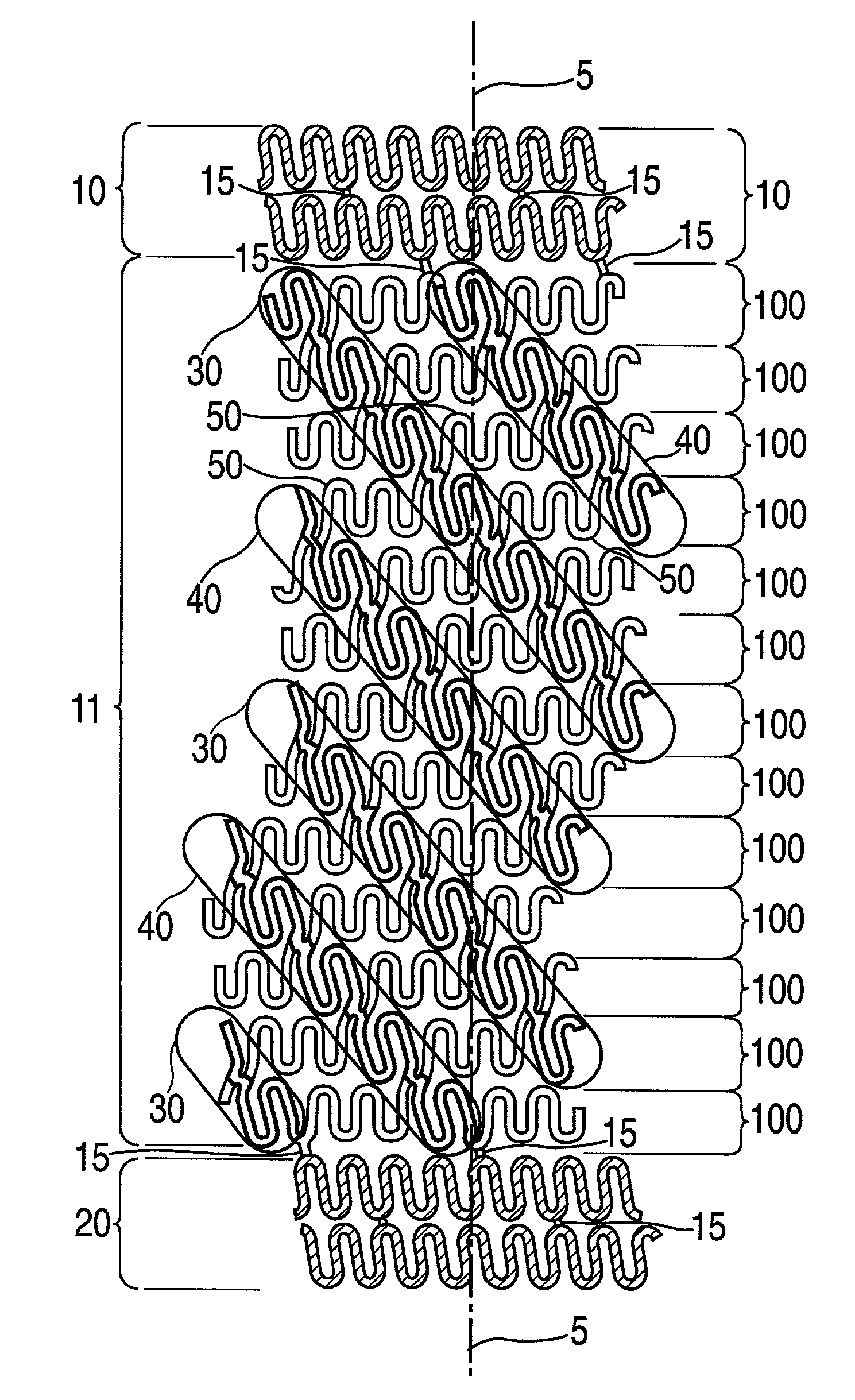
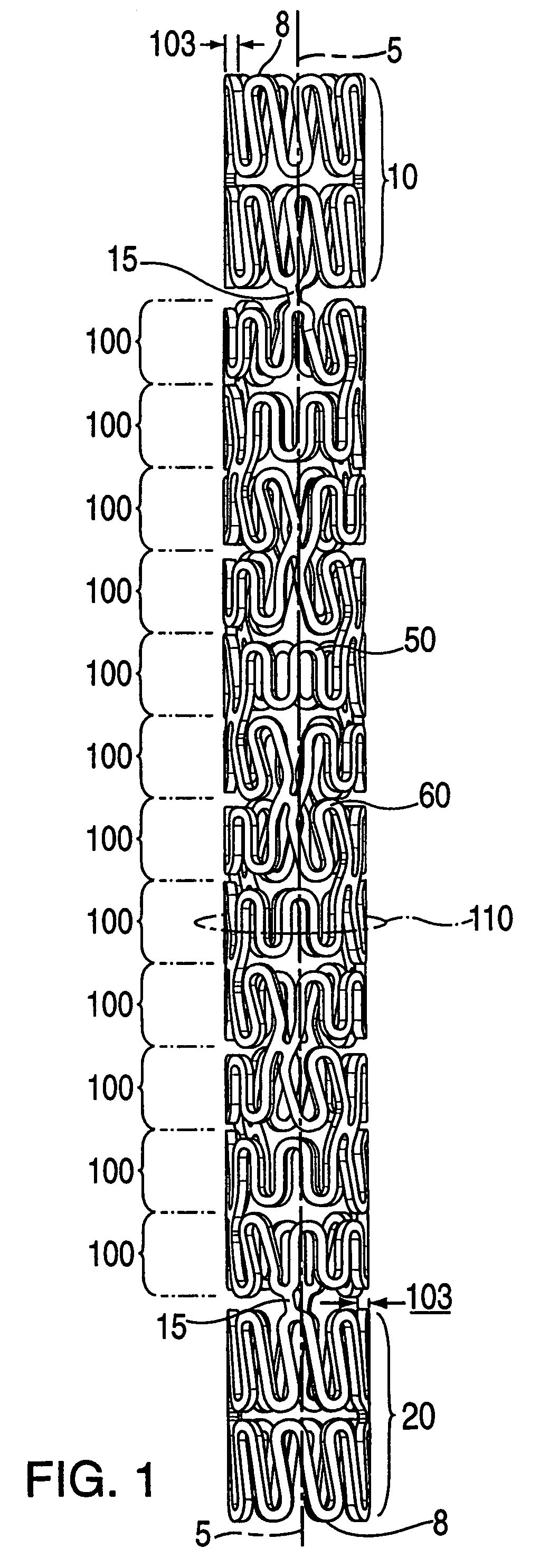
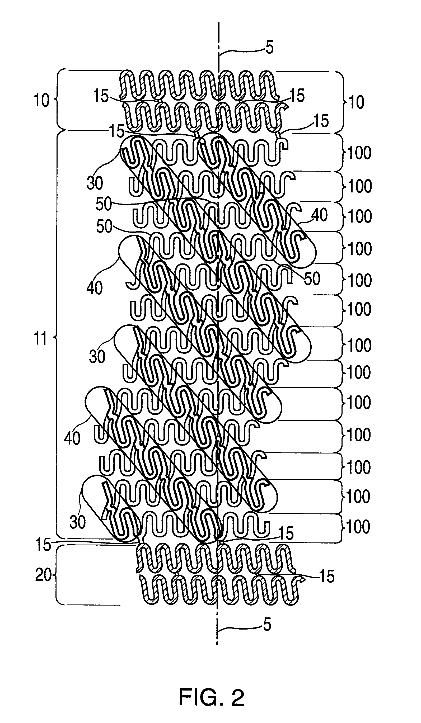
[0027]The present invention is directed to an expandable stent, as well as a method of manufacturing the stent. In one embodiment, as is shown in FIGS. 1 and 2, the stent comprises a generally cylindrical shaped main body section 11 having a cylindrical axis 5 and a wall thickness 103. The wall thickness 103 may optionally be uniform throughout the stent. The main body section 11 is comprised of a plurality of helical segments 30 and 40 and a plurality of main body cylindrical elements 100, each having cylindrical axes (not shown) that are collinear with the main body cylindrical axis 5. The main body cylindrical elements 100 are each comprised of circumferential elements 50 that are joined together by the helical segments 30 and 40 to form individual cylinders 100.

[0028]The stent may also have a first endzone 10 and a second endzone 20 that straddle the body section 11. In some embodiments, such as the one shown in FIG. 1, the endzones 10 and 20 may advantageously provide the stent...


PUM


Abstract

An expandable stent comprised of a plurality of helical segments is disclosed. In one embodiment, the stent is generally cylindrical in shape having a cylindrical axis, and comprises a first and second set of helical segments. The helical segments in the first set are substantially parallel and have a first pitch forming a first helical angle with respect to the cylindrical axis. The helical segments in the second set are also generally parallel to each other and form a second pitch that differs from the first pitch, thereby forming a second helical angle with respect to the cylindrical axis. In an alternative embodiment, the stent comprises one set of helical segments and a plurality of circumferential elements that are joined together by the helical segments to form a plurality of cylindrical elements which are joined together to form a stent body. The stent may also have endzones.

Description

[0001]This application claims the benefit of U.S. Provisional Application No. 60 / 254,688, filed on Dec. 11, 2000, which is hereby incorporated in its entirety by reference, and is a continuation-in-part of U.S. patent application Ser. No. 09 / 511,481, filed on Feb. 23, 2000 now U.S. Pat. No. 7,108,714, which is also hereby incorporated in its entirety by reference and which is a continuation of U.S. patent application Ser. No. 09 / 094,402, filed Jun. 10, 1998 —now U.S. Pat. No. 6,117,165.BACKGROUND OF THE INVENTION[0002]1. Field of the Invention[0003]The present invention relates to prosthetic stents. In particular, the present invention relates to stents having helical elements and to methods for manufacturing the stents of the present invention.[0004]2. Description of Related Art[0005]Stents are prosthetic devices that are implanted in the lumen of a vessel inside the body to provide support for the vessel's wall. Structural support from stents is particularly important in angioplas...

Claims


Application Information

Patent Timeline
IPC IPC(8): A61F2/06A61F2/84A61F2/90
CPCA61F2/91A61F2/915A61F2/88A61F2002/91508A61F2002/91516A61F2002/91525A61F2002/91533A61F2002/91541A61F2002/9155A61F2002/91558A61F2002/91583
Inventor ADDONIZIO, SCOTT J.CAMP, JR., DAVID L.BECKER, GARY J.PAZIENZA, JOHN D.
Owner ORBUSNEICH MEDICAL PTE LTD
Why Eureka
Try Eureka