Vertical combined feed/effluent heat exchanger with variable baffle angle

a heat exchanger and vertical technology, applied in the field of heat exchangers, can solve the problems of non-uniform flow velocity, adversely affecting the performance of the heat exchanger, and reducing the dynamic pressure of the second fluid

Inactive Publication Date: 2009-12-10
LUMMUS TECH INC
View PDF14 Cites 26 Cited by
  • Summary
  • Abstract
  • Description
  • Claims
  • Application Information

AI Technical Summary

Problems solved by technology

This causes a reduction in the dynamic pressure of the second fluid and non-uniform flow velocity thereof, which, in combination, adversely affect the performance of the heat exchanger.
For example, a perpendicular position of the baffles relative to the longitudinal axis of the shell results in a relatively inefficient heat transfer rate/pressure drop ratio.
Additionally, such baffle arrangements produce flow bypass through baffle-to-shell and pipe-to-baffle clearances, resulting in flow maldistribution, eddies, back-flow, and higher rates of fouling, among other undesired consequences.
Increasing unit design capacities (economy of scale) requires large volumetric throughput with a resultant impact on the number of shells required to transfer the heat at the limited temperature differentials.
However, due to the flow hydraulics issues, i.e., two phase inlet flow, varying composition and molecular weight of the vapor and li

Method used


Image

  • Vertical combined feed/effluent heat exchanger with variable baffle angle
  • Vertical combined feed/effluent heat exchanger with variable baffle angle
  • Vertical combined feed/effluent heat exchanger with variable baffle angle

Examples


Embodiment Construction

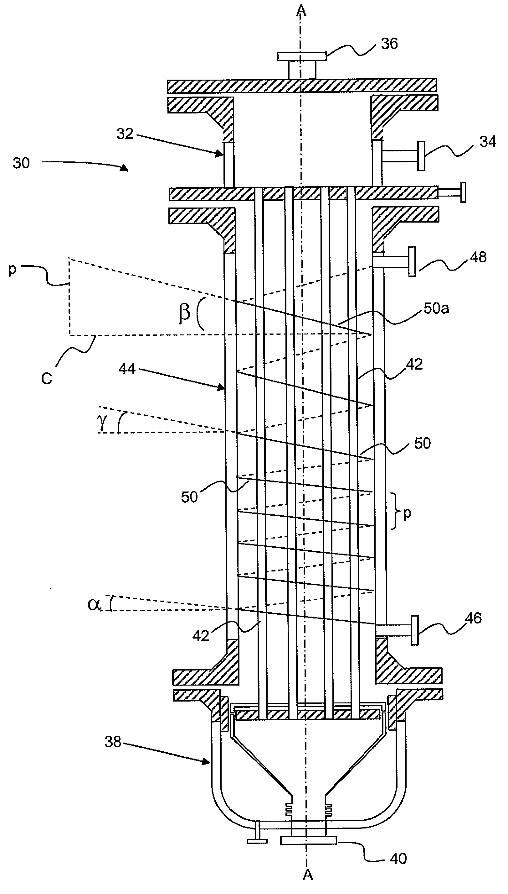
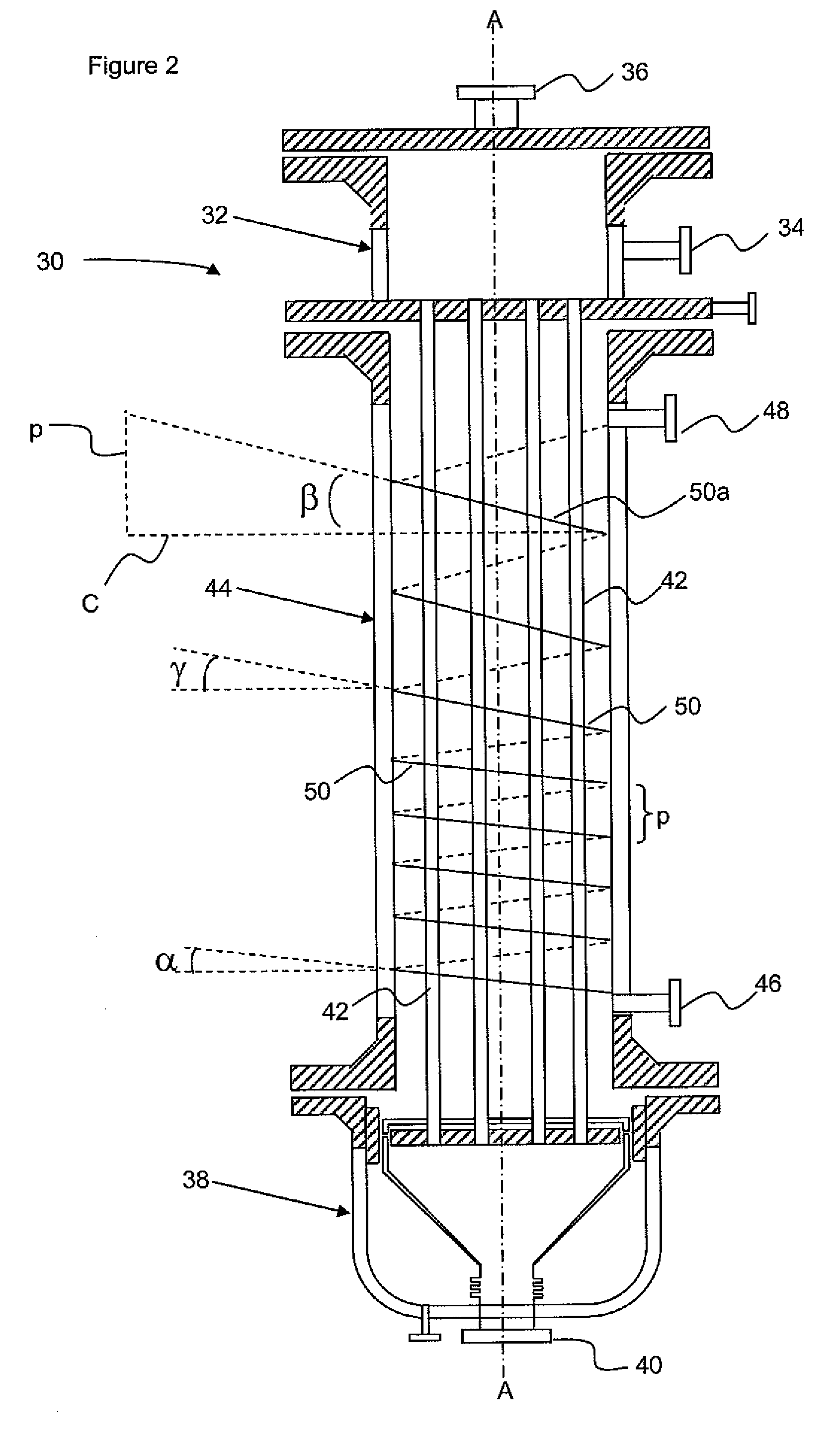
[0017]In one aspect, embodiments herein relate generally to a heat exchanger. More specifically, embodiments disclosed herein relate to a heat exchanger, such as a shell and tube heat exchanger, configured to efficiently process two-phase flow. Even more specifically, embodiments disclosed herein relate to a heat exchanger having baffles configured to direct a shell side fluid flow in a helical flow pattern, where a helix angle of a baffle proximate the inlet is different than a helix angle of a baffle proximate the outlet.

[0018]Heat exchangers having baffles with a varied helix angle according to embodiments disclosed herein have been found to be useful for shellside fluids undergoing a phase change, such as evaporation, condensation, combustion, and the like. For example, for a two-phase inlet flow, such as a vaporizing liquid-vapor mixture, helix angles proximate to the inlet may be provided to maintain sufficient fluid velocity to avoid phase separation of the vapor and the liqu...


PUM


Abstract

A shell and tube heat exchanger, such as a vertical combined feed/effluent heat exchanger (VCFE), including: a shell having a fluid inlet and a fluid outlet; a plurality of baffles mounted in the shell to guide the fluid into a helical flow pattern through the shell; wherein a helix angle α of a baffle proximate the inlet is different than a helix angle β of a baffle proximate the outlet.

Description

FIELD OF THE DISCLOSURE[0001]Embodiments disclosed herein relate generally to a heat exchanger. More specifically, embodiments disclosed herein relate to a heat exchanger, such as a shell and tube heat exchanger, configured to efficiently process two-phase flow.BACKGROUND[0002]Numerous configurations for heat exchangers are known and used for a variety of applications. One of the widely used configurations, a shell and tube heat exchanger, as illustrated in FIG. 1, includes a cylindrical shell 10 housing a bundle of parallel pipes 12, which extend between two end plates 14 so that a first fluid 16 can pass through the pipes 12. Meanwhile, a second fluid 18 flows in and through the space between the two end plates so as to come into contact with the pipes. To provide an improved heat exchange between the two fluids, the flow path of the second fluid 18 is defined by intermediate baffles 20 forming respective passages, which are arranged so that the second fluid flow changes its direc...

Claims


Application Information

Patent Timeline
IPC IPC(8): F28F9/22
CPCF28D7/1607F28F2009/228F28F9/22F28D2021/0064
Inventor KARRS, MARK S.CHUNANGAD, KRISHNAN S.MASTER, BASHIR I.
Owner LUMMUS TECH INC
Why Eureka
Try Eureka