Photoelectric encoder

a technology of photoelectric encoder and encoder, which is applied in the direction of converting sensor output optically, instruments, measurement devices, etc., can solve the problems of reducing signal detection efficiency and the inability to make the optical system smaller, and achieve the effect of preventing a reduction in contras

Active Publication Date: 2008-02-12
MITUTOYO CORP
View PDF6 Cites 7 Cited by
  • Summary
  • Abstract
  • Description
  • Claims
  • Application Information

AI Technical Summary

Benefits of technology

[0011]In view of the foregoing problems, various embodiments of this invention provide a photoelectric encoder that prevents a reduction in contrast by obtaining focus over the entire image plane even if the optical axis is inclined to make an optical system smaller.
[0018]According to the present invention, as shown in FIG. 6, the Scheimpflug rule, which ensures that if the three planes extended from the subject plane, a principal plane of a lens, and the image plane intersect at a single point, focus is obtained over the entire image plane, is satisfied, thereby obtaining focus over the entire image plane. Accordingly, even if the optical axis is inclined to make an optical system smaller, a reduction in contrast can be prevented.

Problems solved by technology

In addition, since the optical axis is perpendicular to the surface plane of the main scale 20, it is impossible to make the optical system smaller.
Therefore, if focus is obtained at the center, for example, blurring occurs at the upper and lower regions, so that a uniform contrast cannot be ensured over the entire light receiving surface, causing the problem of a reduction in signal detection efficiency.

Method used


Image

  • Photoelectric encoder
  • Photoelectric encoder
  • Photoelectric encoder

Examples


first embodiment

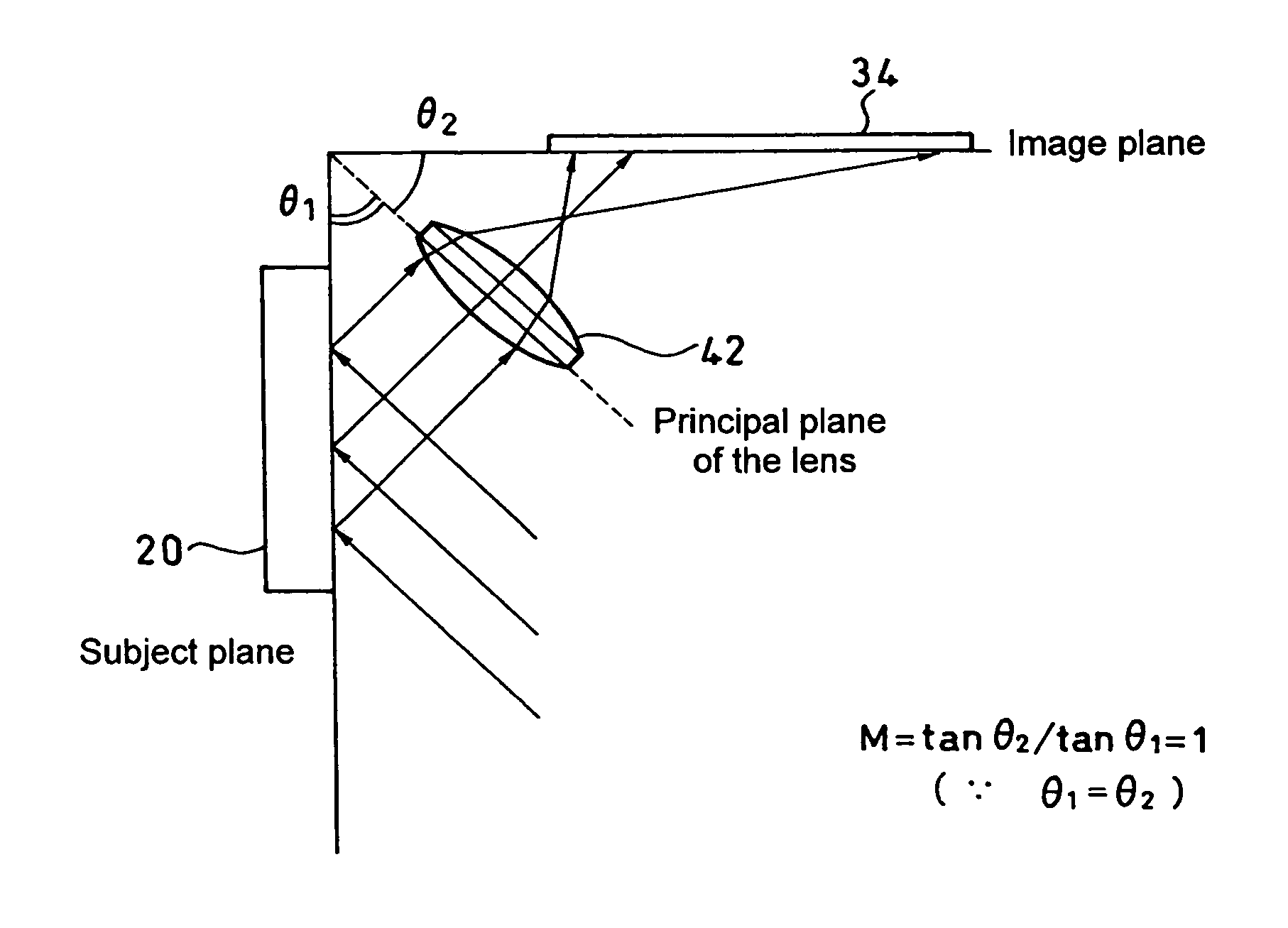
[0038]the invention includes, as shown in FIG. 7, a scale 20, a lens 42, and a light receiving element 34, which are disposed so that a subject plane of the scale 20, a principal plane of the lens 42, and an image plane of the light receiving element 34 satisfy the Scheimpflug rule and an angle θ1 between the subject plane and the principal plane of the lens and an angle θ2 between the principal plane of the lens and the image plane match each other.

[0039]In the present embodiment, since θ1=θ2, the optical magnification of an image is given by

M=tan θ2 / tan θ1=1

implying an optical system with 1× magnification.

[0040]In particular, when θ1=θ2=45°, the sum θ1+θ2 comes to 90°, so that assembly becomes easy.

[0041]Further, as a modification shown in FIG. 8, an aperture 44 may be inserted at a focal point of the lens 42 to constitute a telecentric optical system 40.

second embodiment

[0042]As in a second embodiment shown in FIG. 9, it is also possible to constitute an optical system with M× magnification by setting as θ1≠θ2.

third embodiment

[0043]Next, the present invention will be described in detail with reference to FIG. 10.

[0044]The present embodiment relates to a photoelectric encoder that has a lens optical system 50 configured such that a second lens 48, which is the same as the lens 42 (referred to also as “first lens”), is inserted on the opposite side of the first lens 42 in a reverse fashion so that its focal point is located at focal point of the first lens 42. In this photoelectric encoder, the scale 20, the lens optical system 50, and the light receiving element 34 are disposed so that the subject plane, a plane (referred to as “focal plane”) which includes the focal points of the first lens 42 and the second lens 48 and being perpendicular to optical axis, and the image plane satisfy the Scheimpflug rule and the angle θ1 between the subject plane and the focal plane and the angle θ2 between the focal plane and the image plane match each other.

[0045]In the present embodiment, since the first lens 42 on th...


PUM


Abstract

A photoelectric encoder that has a lens optical system including a lens inserted between a main scale and a light receiving element. In the photoelectric encoder, three planes extended from a surface of the main scale, a principal plane of the lens, and an image plane of the light receiving element are disposed so as to intersect at a single point and satisfy the Scheimpflug rule. Focus can thereby be obtained over the entire image plane, so that a reduction in contrast is prevented, even if the optical axis is inclined to make an optical system smaller.

Description

CROSS-REFERENCE TO RELATED APPLICATION[0001]The disclosure of Japanese Patent Application No. 2005-69281 filed on Mar. 11, 2005 including specifications, drawings and claims is incorporated herein by reference in its entirety.BACKGROUND OF THE INVENTION[0002]1. Field of the Invention[0003]The present invention relates to a photoelectric encoder. In particular, the invention relates to improvements in a photoelectric encoder that has a telecentric optical system wherein a lens and an aperture are inserted between a main scale and a light receiving element.[0004]2. Description of the Related Art[0005]As described in Japanese Patent Laid-Open Publication No. 2004-264295 and as shown in FIG. 1, a photoelectric encoder is designed in which a lens optical system (telecentric optical system) 40, comprising a lens 42 and an aperture 44 that functions as a telecentric optical diaphragm, is inserted between a main scale 20 and a light receiving element array 34 constituting a light receiving ...

Claims


Application Information

Patent Timeline
Patent Type & Authority Patents(United States)
IPC IPC(8): G01D5/34G01B11/14
CPCG01D5/34715
Inventor MIZUTANI, MIYAKONAGAHAMA, TATSUYA
Owner MITUTOYO CORP
Why Eureka
Try Eureka