Reflective screen and manufacturing method thereof

a technology of reflector and screen, which is applied in the field of reflector, can solve the problems of projector not being widely distributed in the general household, user's inability to accurately view a desired image, etc., and achieve the effects of reducing the brightness of projection light, reducing the manufacturing cost of the screen, and improving the contrast of an imag

Active Publication Date: 2010-04-29
LG ELECTRONICS INC
View PDF12 Cites 7 Cited by
  • Summary
  • Abstract
  • Description
  • Claims
  • Application Information

AI Technical Summary

Benefits of technology

[0021]According to an embodiment, a screen where reduction in brightness of projection light is small and the contrast o

Problems solved by technology

However, since these screens reflects not only projection light from the projector but also external light, the contrast of an image reduces at an atmosphere where an external light level is high, so that a user cannot accurately view a desired image.
For this limitation, the projector has not been widely distributed for a general household and has required a separate installation space.
However, in this case, since not only external light but also projection light from the projector reduces by the light diffusion layer, a white color level falls

Method used


Image

  • Reflective screen and manufacturing method thereof
  • Reflective screen and manufacturing method thereof
  • Reflective screen and manufacturing method thereof

Examples


embodiment 1

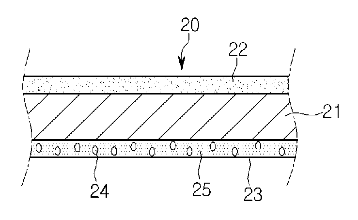
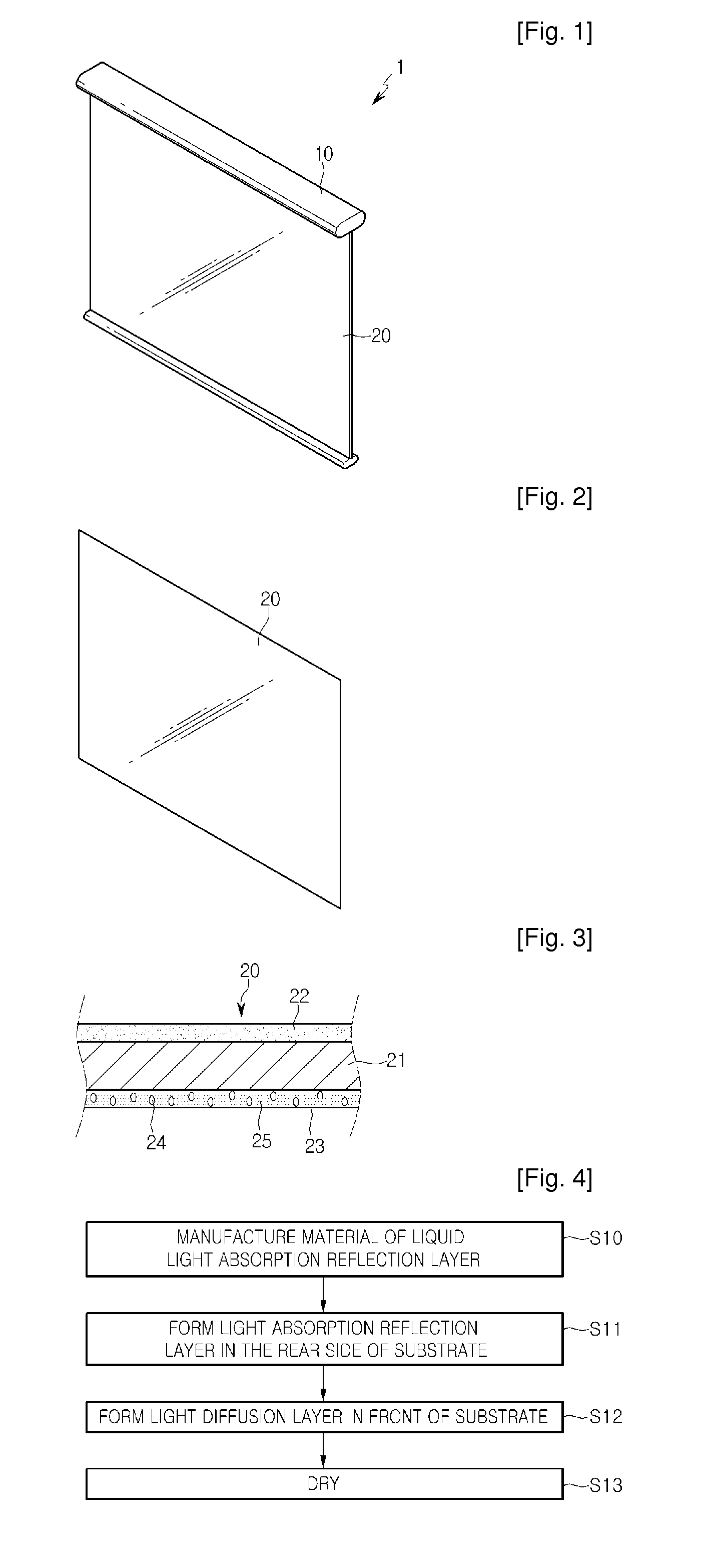
[0036]FIG. 3 is a cross-sectional view of a reflective screen according to an embodiment.

[0037]Referring to FIG. 3, the reflective screen includes a substrate 21, a light absorption reflection layer 23 formed on the rear side of the substrate 21, and a light diffusion layer 22 formed on the front side of the substrate 21. In the drawing, an arrow indicates the incident direction of projection light of a projector.

[0038]The above-mentioned elements are described below in more detail.

[0039]Substrate 21

[0040]The substrate 21 has a sufficient area on which light projected from the projector is displayed, and is formed of a transparent material. The substrate 21 can be formed of polyvinyl chloride (PVC), polyethylene terephthalate (PET), polycarbonate (PC), acryl, and polyester which have light transmission degree of 90% or more. Here, a material such as PET having low flexibility may be applied to the screen fixed on the wall surface illustrated in FIG. 2.

[0041]Light Absorption Reflecti...

embodiment 2

[0075]Other parts of another embodiment are the same as those of the previous embodiment, and only difference is the construction of the light diffusion layer. Accordingly, descriptions of the same parts are omitted.

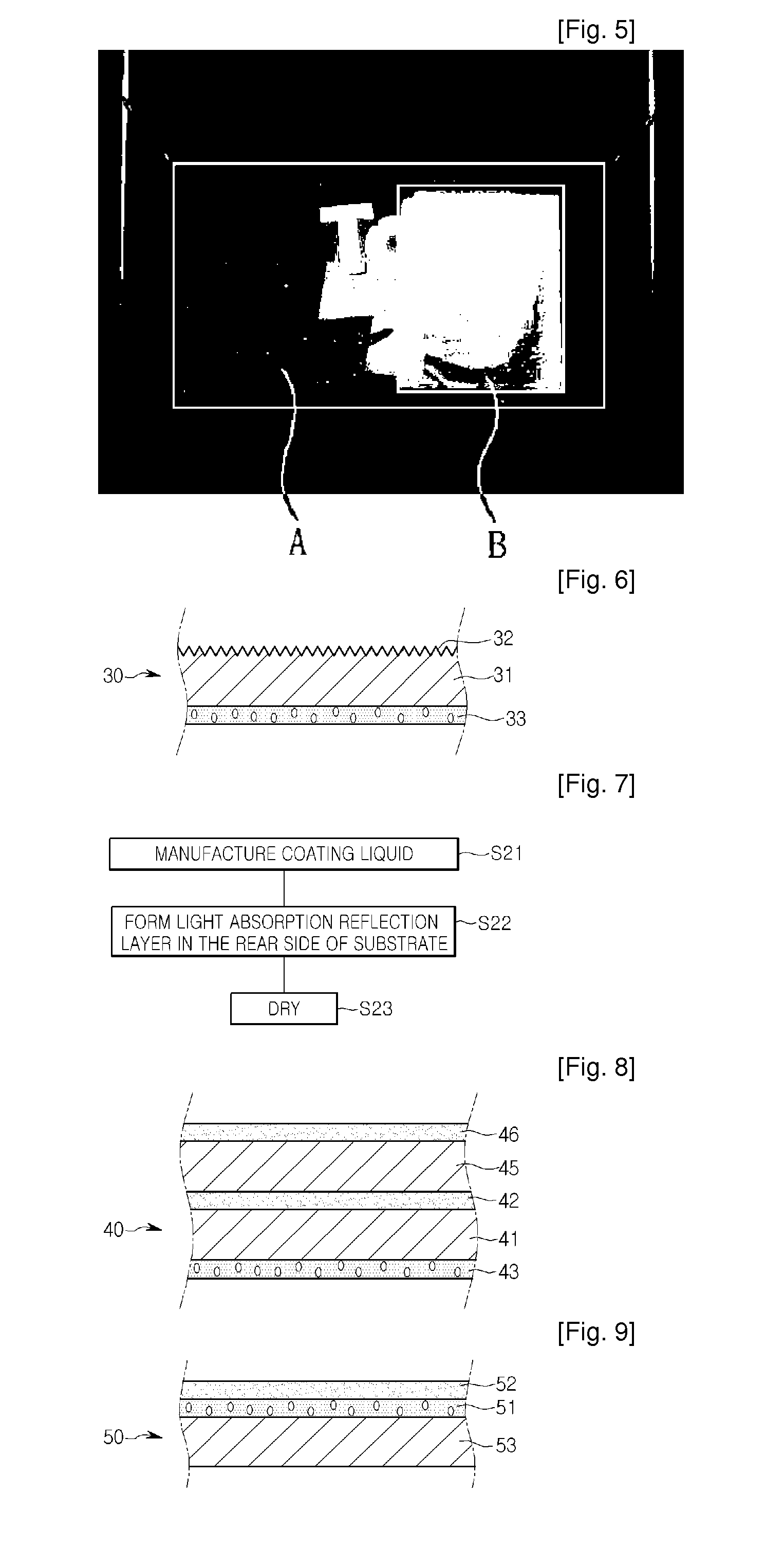
[0076]FIG. 6 is a cross-sectional view of a reflective screen according to another embodiment, and FIG. 7 is a flowchart explaining a method for manufacturing a reflective screen according to another embodiment.

[0077]Referring to FIG. 6, the reflective screen 30 includes a substrate 31, a light absorption reflection layer 33 formed on the rear side of the substrate 31, and an unevenness portion 32 formed on the front side of the substrate 31. The unevenness portion 32 can serve as a light diffusion layer.

[0078]The unevenness portion 32 has so fine unevenness patterns as to generate a light diffusion operation. The substrate 31 on which the unevenness portion 32 is provided can be manufactured in the following process.

[0079]The substrate 31 can be manufactured in a method...

embodiment 3

[0082]Since still another embodiment is mostly the same as the previous embodiments, only different parts are described in detail and description of the same parts are omitted.

[0083]FIG. 8 is a cross-sectional view of a reflective screen according to still another embodiment.

[0084]Referring to FIG. 8, the reflective screen 40 includes a second substrate 41, a light absorption reflection layer 43 formed on the rear side of the second substrate 41, a second light diffusion layer 42 formed on the front side of the second substrate 41, a first substrate 45 formed on the front side of the second light diffusion layer 42, and a first light diffusion layer 46 formed on the first substrate 45.

[0085]As apparent from the drawing, the light diffusion layers are repeatedly formed in the present embodiment. In the case where the light diffusion layers 42 and 46 are repeatedly formed, light diffusion is enhanced. Therefore, the contrast of an image reduces due to brightness increase of external l...


PUM


Abstract

Provided is a reflective screen. The reflective screen can be widely and commercially used, easily manufactured at low costs, and realize a sufficient reflection image. The reflective screen includes a substrate, a light diffusion layer in front of the substrate, a light reflecting material reflecting projection light, a light absorbing material absorbing external light, and a light absorption reflection layer containing at least the light reflecting material and the light absorbing material together. The light absorption reflection layer being disposed in the rear of the substrate.

Description

TECHNICAL FIELD[0001]The present disclosure relates to a reflective screen reflecting projected light to display an image, and a method for manufacturing the reflective screen.BACKGROUND ART[0002]A projector can be exemplified as a display device that is increasingly used recently. Advantageously, the projector can easily realize a large-sized screen. The projector operates in the following way, in which light emitted from a light source is synthesized by a light synthesizer to become image light, and this image light is projected onto a screen through a lighting system such as a lens.[0003]Representative examples of a screen displaying an image by the projector include a transmissive screen where an image is projected from the rear of the screen, and a reflective screen reflecting projection light projected from a projector in front of the screen to allow a projection image to be viewed by reflected light.[0004]Representative examples of a related art reflective screen include a be...

Claims


Application Information

Patent Timeline
IPC IPC(8): G03B21/60G03B21/56B05D5/06
CPCY10T428/25G03B21/60G03B21/56
Inventor KANG, HEE BUM
Owner LG ELECTRONICS INC
Why Eureka
Try Eureka