Reflection-type screen, projection system, front projection television system, and reflection-type screen manufacturing method

a technology of projection system and screen, which is applied in the direction of television system, picture reproducer using projection device, instrument, etc., can solve the problems of reducing contrast and increasing black luminance in screen characteristics, and achieve the effect of convenient manufacturing

Inactive Publication Date: 2011-10-13
SEIKO EPSON CORP
View PDF3 Cites 6 Cited by
  • Summary
  • Abstract
  • Description
  • Claims
  • Application Information

AI Technical Summary

Benefits of technology

[0024]According to this method, the material of the reflection films such as aluminum is diagonally deposited from the position facing to the reflection areas determined for each curved portion of the base to form the reflection films. Thus, the reflection films can be formed on the reflection areas with self-alignment by establishing the relationship between the position of the evaporation source where the material of the reflection films i

Problems solved by technology

In this case, the reflection of the external light toward the image viewing side may increase the black luminance in the screen characteristics and lower the contrast.
Moreover, while other materials such as magnesium fluoride ha

Method used


Image

  • Reflection-type screen, projection system, front projection television system, and reflection-type screen manufacturing method
  • Reflection-type screen, projection system, front projection television system, and reflection-type screen manufacturing method
  • Reflection-type screen, projection system, front projection television system, and reflection-type screen manufacturing method

Examples


embodiment

Advantages of Embodiment

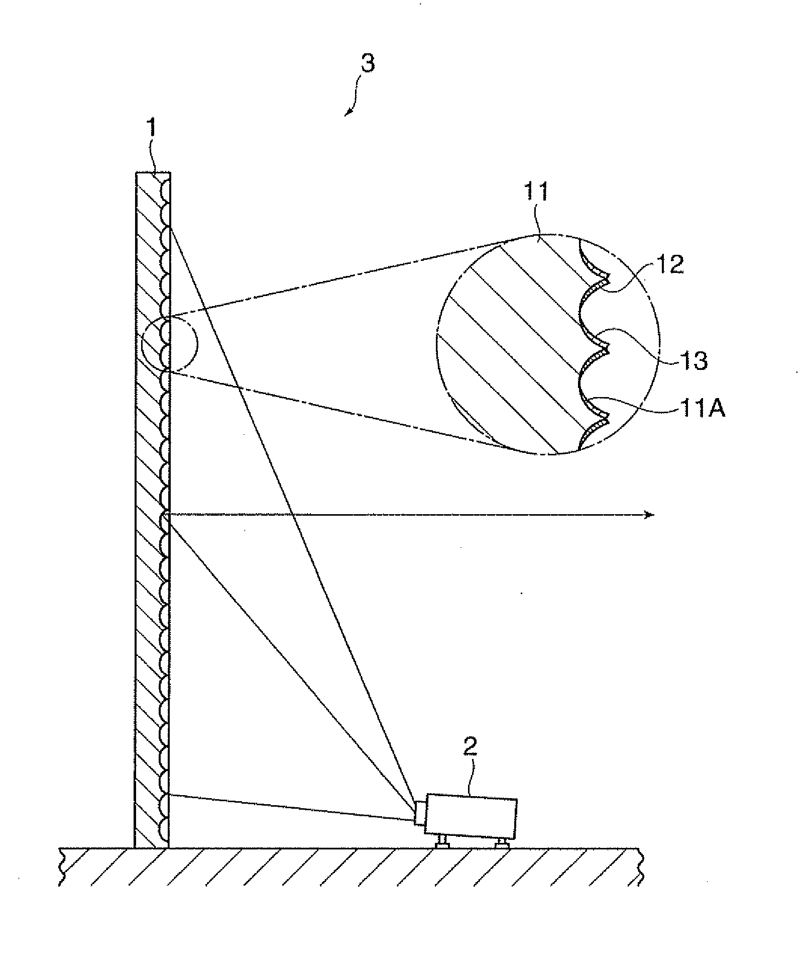
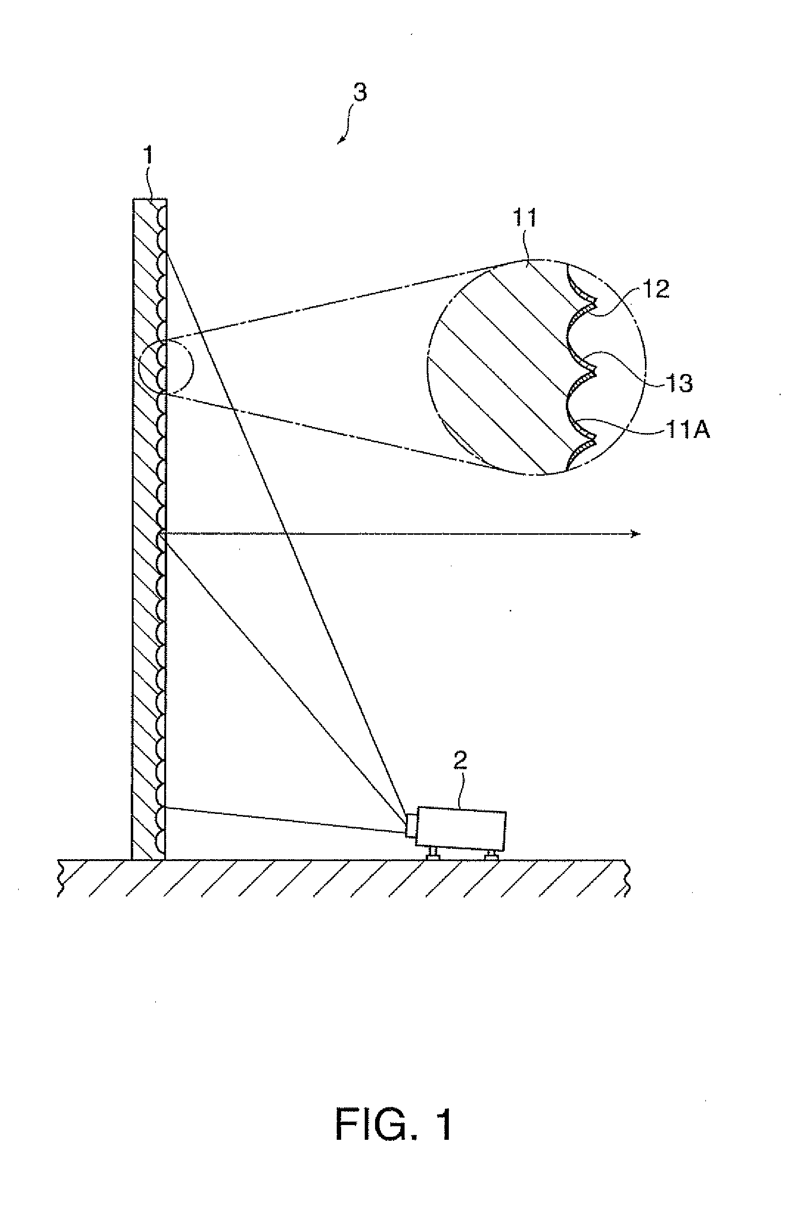
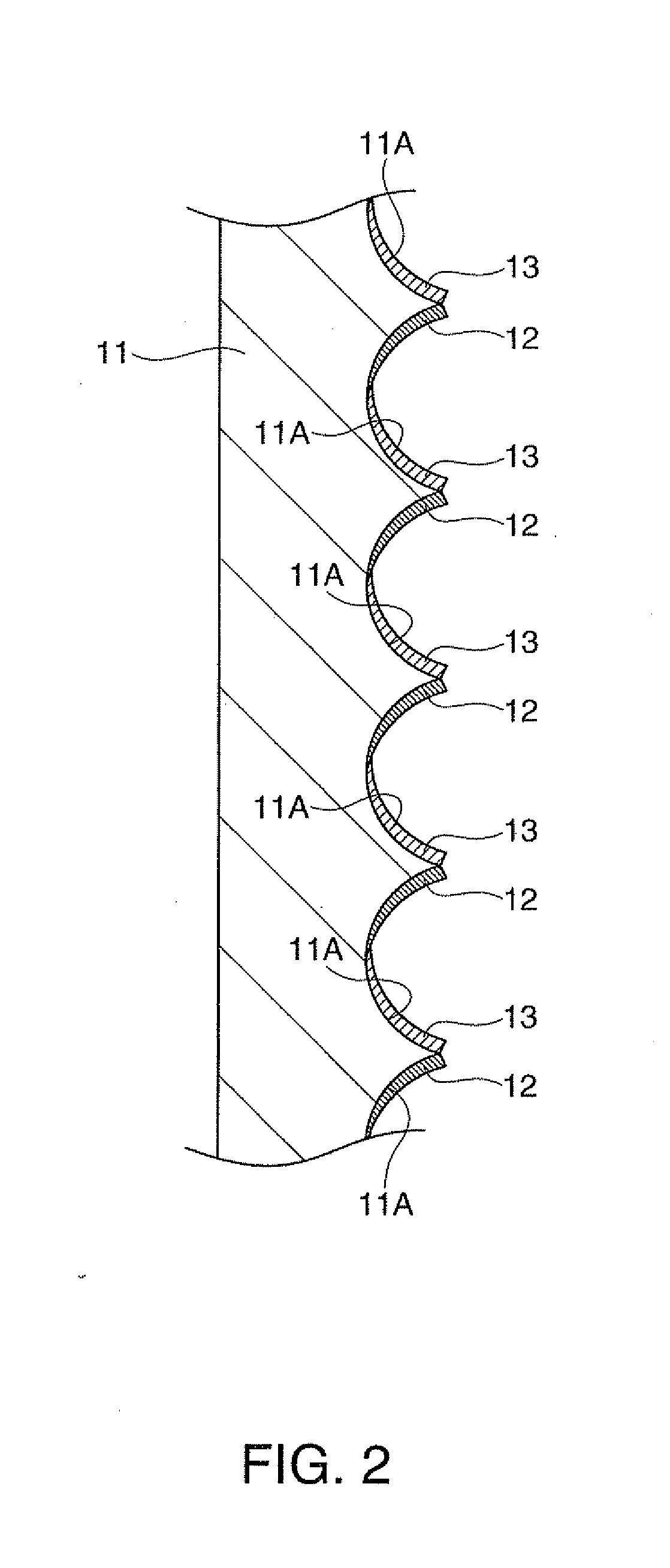
[0073]According to this embodiment, the reflection films 12 are formed on the reflection areas determined on the plural concave portions 11A having concave surfaces and provided on the base 11. In addition, the anti reflection films 13 having the plural diagonally deposited transparent columnar components 13A are formed on the non-reflection areas determined on the concave portions 11A of the base 11.

[0074]In this structure, external light applied to the non-reflection areas to which projection light is not applied is not reflected toward the image viewing side by the function of the anti-reflection films 13. Thus, the black luminance of the base 11 does not increase, thereby preventing lowering of the contrast of the projection light reflected by the reflection films 12 with high efficiency. Accordingly, the contrast can be easily raised by the simple structure which has the plural anti-reflection films 13 containing the plural diagonally deposited transpare...

modified examples

[0083]The invention is not limited to the embodiment described herein but includes modifications, improvements and the like without departing from the scope of the invention.

[0084]According to this embodiment, the reflection films 12 are formed with self-alignment by diagonal deposition. However, the reflection films 12 may be deposited on the reflection areas of the concave portions 11A by masking, or may be formed on the reflection areas by etching after deposited on the entire areas of the concave portions 11A. Alternatively, the anti-reflection films 13 may be formed on the non-reflection areas by diagonal deposition after deposition of the reflection films 12 on the entire areas of the concave portions 11A.

[0085]According to this embodiment, the structure which includes the concave portions 11A having the concave surfaces on the base 11 has been discussed as an example. However, a plurality of curved portions having convex surfaces may be provided on the base 11, for example. I...

example

[0092]An example of the invention and a comparison example are now described for more specific explanation of the invention.

[0093]It should be understood that the invention is not limited to this example or associated descriptions shown herein.


PUM

PropertyMeasurementUnit
Thicknessaaaaaaaaaa
Areaaaaaaaaaaa
Transparencyaaaaaaaaaa

Abstract

A reflection-type screen which reflects projection light from a projector is provided. The screen includes a base one surface of which has a plurality of curved portions having concave or convex surfaces. Each of the curved portions of the base has a reflection area and a non-reflection area. A reflection film is formed on each of the reflection areas. An anti-reflection film is formed on each of the non-reflection areas. Each of the anti-reflection films has a plurality of transparent columnar components.

Description

BACKGROUND[0001]1. Technical Field[0002]The present invention relates to a reflection-type screen, a projection system, a front projection television system, and a reflection-type screen manufacturing method.[0003]2. Related Art[0004]A reflection-type screen which receives projection light from a projector or the like and reflects the projection light to display a visually recognizable image is known. A known example of this reflection-type screen is a type which has a number of convex units having uniform shapes disposed two-dimensionally on the front surface of a screen base to which an image is projected (JP-A-2006-215162).[0005]The reflection-type screen disclosed in JP-A-2006-215162 has a reflection surface only on a part of each front surface area of the units facing to the incident direction of the projection light. For example, when the projection image is applied to the reflection-type screen in the diagonally upward direction from the projector disposed on the front side o...

Claims


Application Information

Patent Timeline
IPC IPC(8): H04N9/31B23P11/00G03B21/56G03B21/00G02B5/08G02B5/10G03B21/60
CPCY10T29/49826G03B21/602
Inventor SHIMIZU, NOBUO
Owner SEIKO EPSON CORP
Why Eureka
Try Eureka