Adjusting on-time for a discontinuous switching voltage regulator

a switching voltage regulator and on-time technology, applied in the field of voltage regulators, can solve the problems of increasing the cost and complexity of the switching voltage regulator, reducing power efficiency,

Active Publication Date: 2008-02-12
WESTERN DIGITAL TECH INC
View PDF54 Cites 134 Cited by
  • Summary
  • Abstract
  • Description
  • Claims
  • Application Information

AI Technical Summary

Problems solved by technology

However, employing a linear transfer function to adjust the peak current threshold may decrease power efficiency due to an increase in the transient response time, and it may also lead to instability.
In addition, employing an analog current sensor and a programmable analog current comparator can increase the cost and complexity of the switching voltage regulator.

Method used


Image

  • Adjusting on-time for a discontinuous switching voltage regulator
  • Adjusting on-time for a discontinuous switching voltage regulator
  • Adjusting on-time for a discontinuous switching voltage regulator

Examples


Embodiment Construction

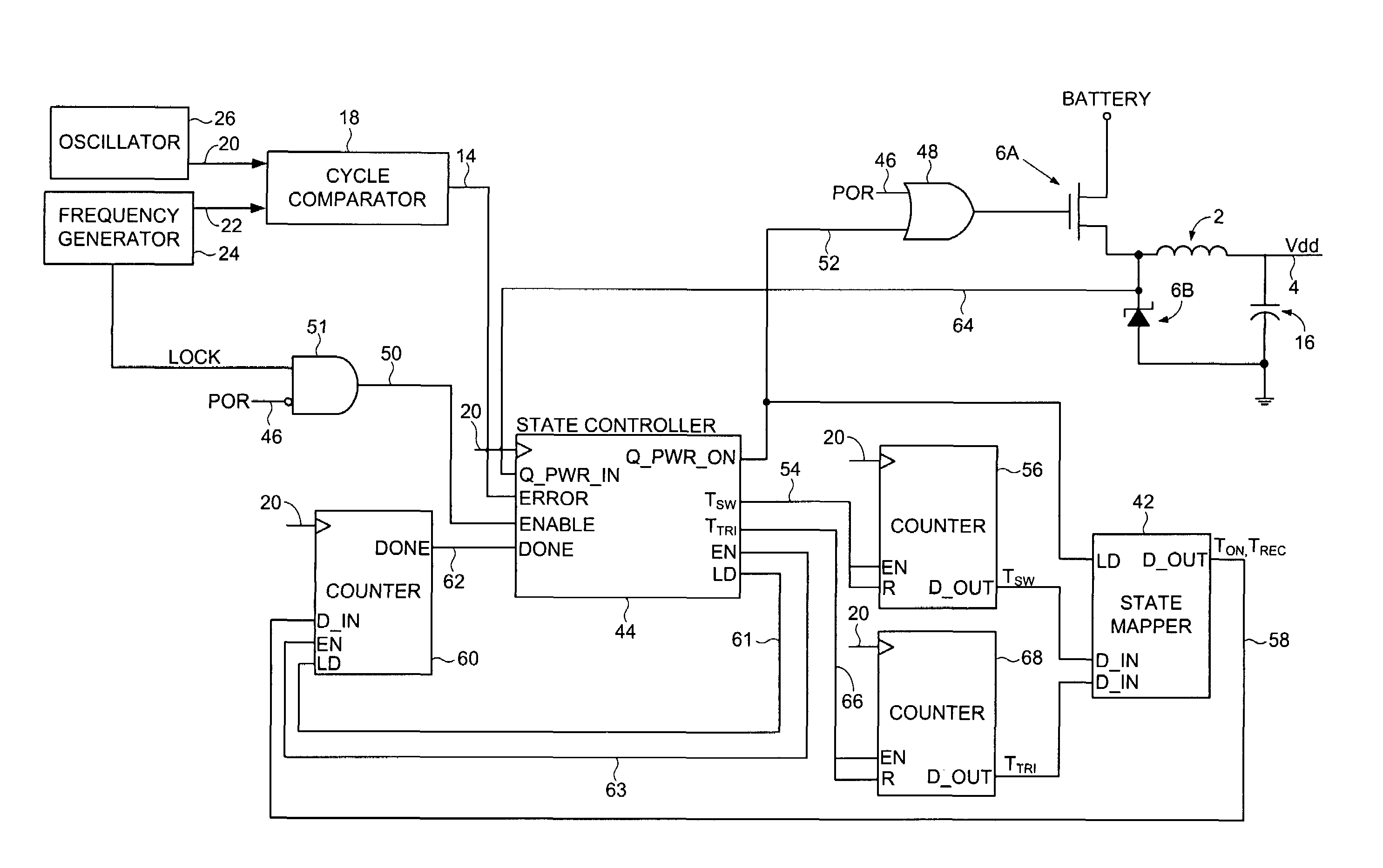
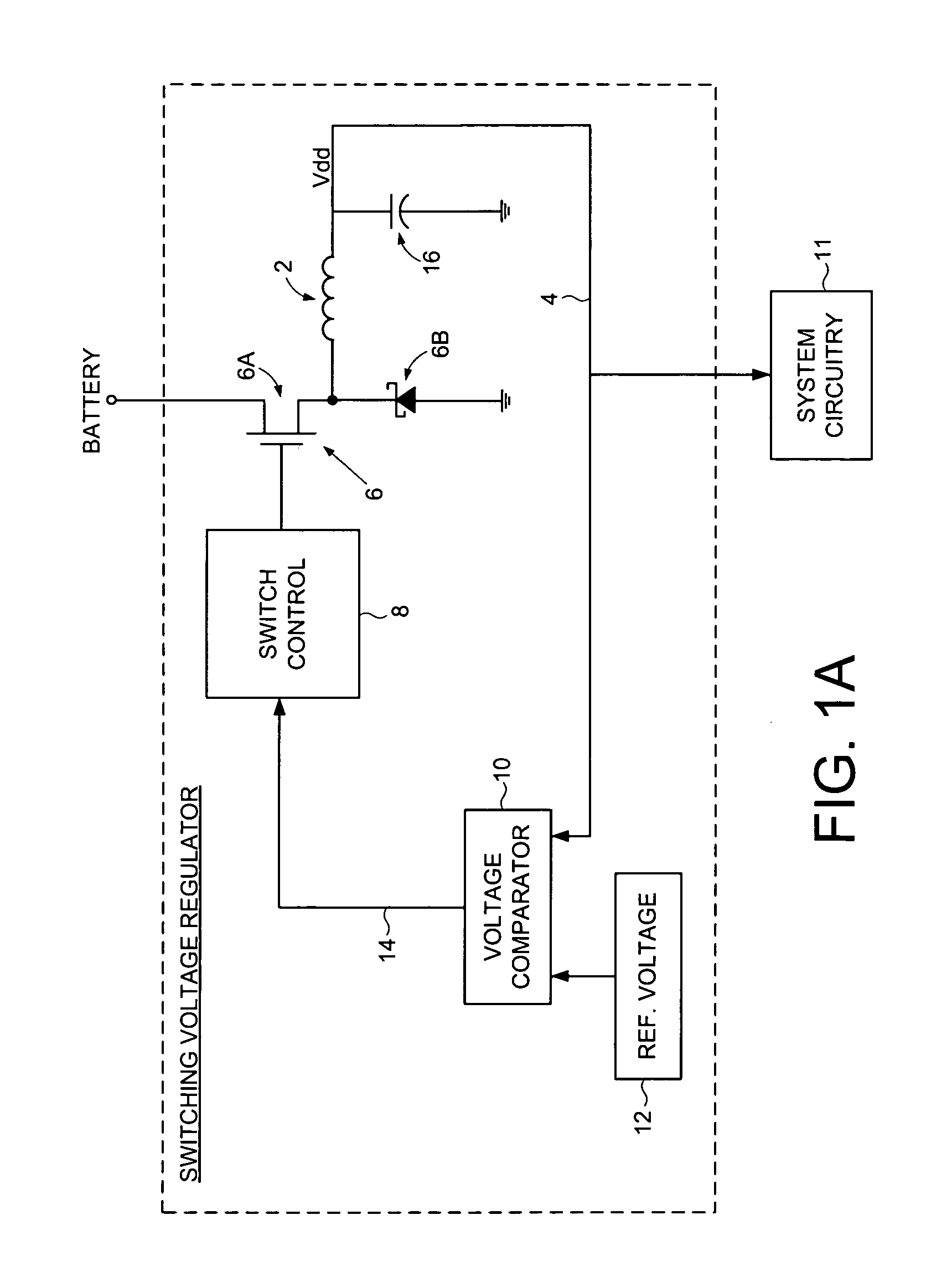
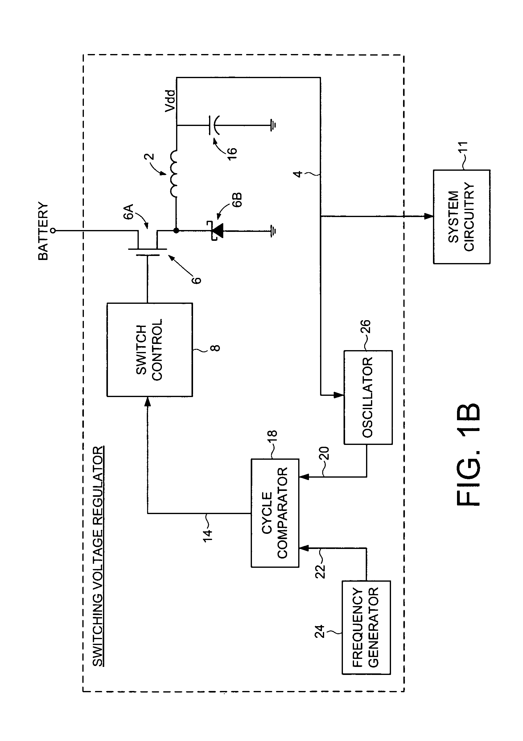
[0024]FIG. 1A shows an embodiment of the present invention comprising a discontinuous switching voltage regulator including a charging element 2 operable to generate an output voltage 4, switching circuitry 6 coupled to the charging element 2, and switch control circuitry 8 operable to control the switching circuitry 6 to configure the charging element 2 during a cycle, including to charge the charging element 2 for an on-time, discharge the charging element 2 for a discharge time, and tristate the charging element 2 for a tristate time. In operation, the on-time is initialized to a first on-time, and a first switch time is measured comprising the first on-time and a first discharge time of a first cycle. A first tristate time of the first cycle is also measured, and a first ratio of the first tristate time to the first switch time is determined. The first ratio is compared to a first ratio threshold, and the on-time is adjusted to a second on-time if the first ratio exceeds the fir...


PUM


Abstract

A discontinuous switching voltage regulator is disclosed including a charging element operable to generate an output voltage, switching circuitry coupled to the charging element, and switch control circuitry to configure the charging element during a cycle, including to charge the charging element for an on-time, discharge the charging element for a discharge time, and tristate the charging element for a tristate time. In operation, the on-time is initialized to a first on-time, and a first switch time is measured comprising the first on-time and a first discharge time of a first cycle. A first tristate time of the first cycle is measured, and a first ratio of the first tristate time to the first switch time is determined. The first ratio is compared to a first ratio threshold, and the on-time is adjusted to a second on-time if the first ratio exceeds the first ratio threshold.

Description

CROSS REFERENCE TO RELATED PATENTS AND PATENT APPLICATIONS[0001]This application is related to U.S. patent application Ser. No. 11 / 393,425 filed on Mar. 30, 2006, entitled “SWITCHING VOLTAGE REGULATOR COMPRISING A CYCLE COMPARATOR FOR DYNAMIC VOLTAGE SCALING” the disclosure of which is incorporated herein by reference.BACKGROUND OF THE INVENTION[0002]1. Field of the Invention[0003]The present invention relates to voltage regulators. More particularly, the present invention relates to adjusting the on-time for a discontinuous switching voltage regulator.[0004]2. Description of the Prior Art[0005]Discontinuous switching voltage regulators comprise a charging element that is charged / discharged and then tristated over a cycle that begins when an error signal exceeds a threshold. For example, the charging time may begin when an output voltage falls below a reference voltage, or when a propagation oscillation signal representing a propagation delay of a digital circuit falls below a refer...

Claims


Application Information

Patent Timeline
Patent Type & Authority Patents(United States)
IPC IPC(8): G05F1/575G05F1/56
CPCH02M3/156H02M3/157
Inventor BENNETT, GEORGE J.
Owner WESTERN DIGITAL TECH INC
Why Eureka
Try Eureka