Ray beam guiding apparatus and ray inspection system having the same

a technology of guiding apparatus and guiding apparatus, which is applied in the direction of radiation/particle handling, nuclear engineering, and diaphragm/collimeter use, etc. it can solve the problems of deteriorating inspection quality, reducing inspection quality, and reducing the thickness of the ray shielding layer inside the guiding apparatus. , to achieve the effect of improving inspection quality, easy control of the field angle of the ray beam, and reducing the thickness of the ray shielding layer

Active Publication Date: 2008-02-12
NUCTECH CO LTD +1
View PDF7 Cites 1 Cited by
  • Summary
  • Abstract
  • Description
  • Claims
  • Application Information

AI Technical Summary

Benefits of technology

[0010]The ray beam guiding apparatus according to the embodiments of the present invention can adjust not only the profile (e.g. sizes, and shapes) of the ray beam but also centering of the ray beam relative to the detector array, so that the inspection quality can be improved and the thickness of the ray shielding layer inside the ray beam guiding apparatus can be reduced. The ray beam guiding apparatus according to the present invention is applicable to a ray inspection system for making security inspection of liquid matters.
[0020]With the ray beam guiding apparatus having the above mentioned structures, the following advantages can be achieved with the present invention.
[0021]1. The field angle of the ray beam can be controlled easily and effectively.
[0022]2. It is possible to adjust the width and height (i.e. sizes in the horizontal and vertical directions) of the ray beam.
[0023]3. It is easy to center the target spot of the ray generator (ray source).
[0024]4. The thickness of the ray shielding layer of the ray beam guiding apparatus can be reduced, with the inspection quality improved as well.

Problems solved by technology

The conventional ray beam guiding apparatus for limiting the X-ray beam to a substantial fan shape can neither change accurately width of the ray beam and nor adjust conveniently centering of the ray beam.
Therefore, the X-rays tend to be deflected and scattered, so that the inspection quality is deteriorated and the thickness of the ray shielding layer inside the guiding apparatus is needed to be increased.

Method used


Image

  • Ray beam guiding apparatus and ray inspection system having the same
  • Ray beam guiding apparatus and ray inspection system having the same
  • Ray beam guiding apparatus and ray inspection system having the same

Examples


Embodiment Construction

[0030]Embodiments of the present invention will be described in detail with reference to drawings, the same elements are denoted by like reference numerals throughout the descriptions. The embodiments described herein are explanatory and illustrative and shall not be construed to limit the present invention.

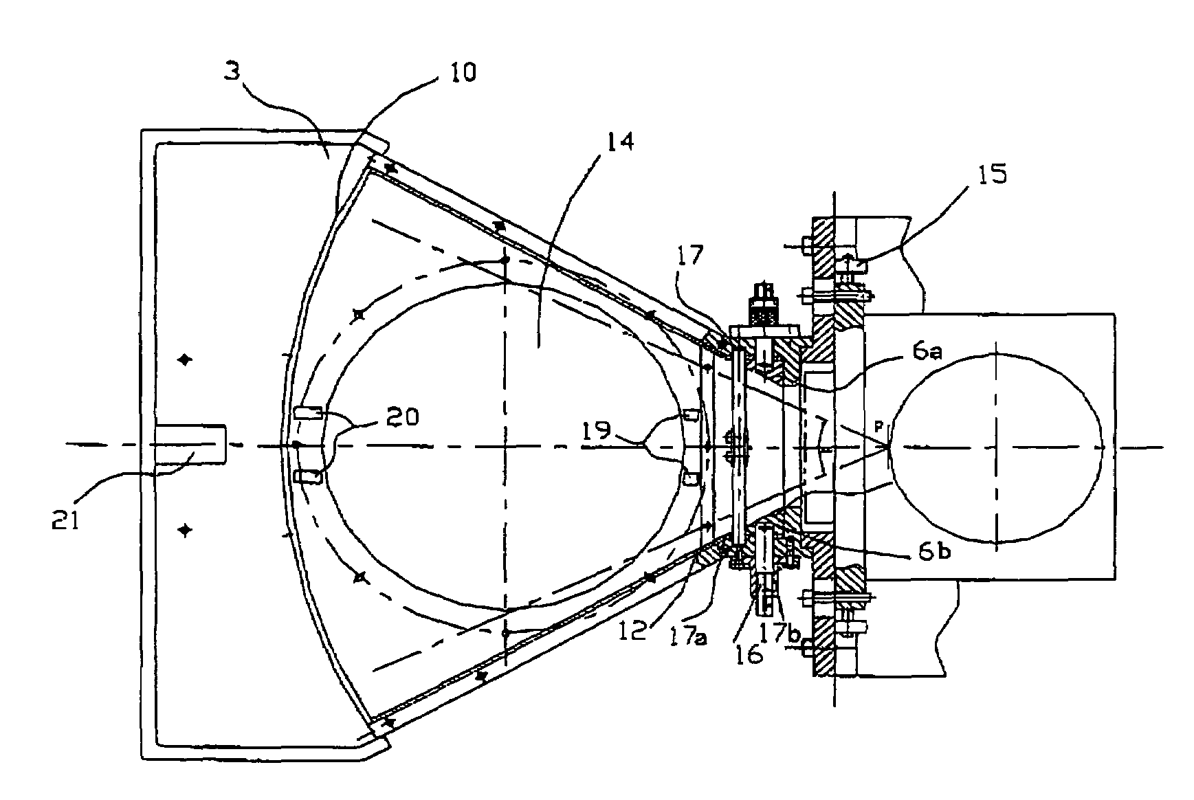
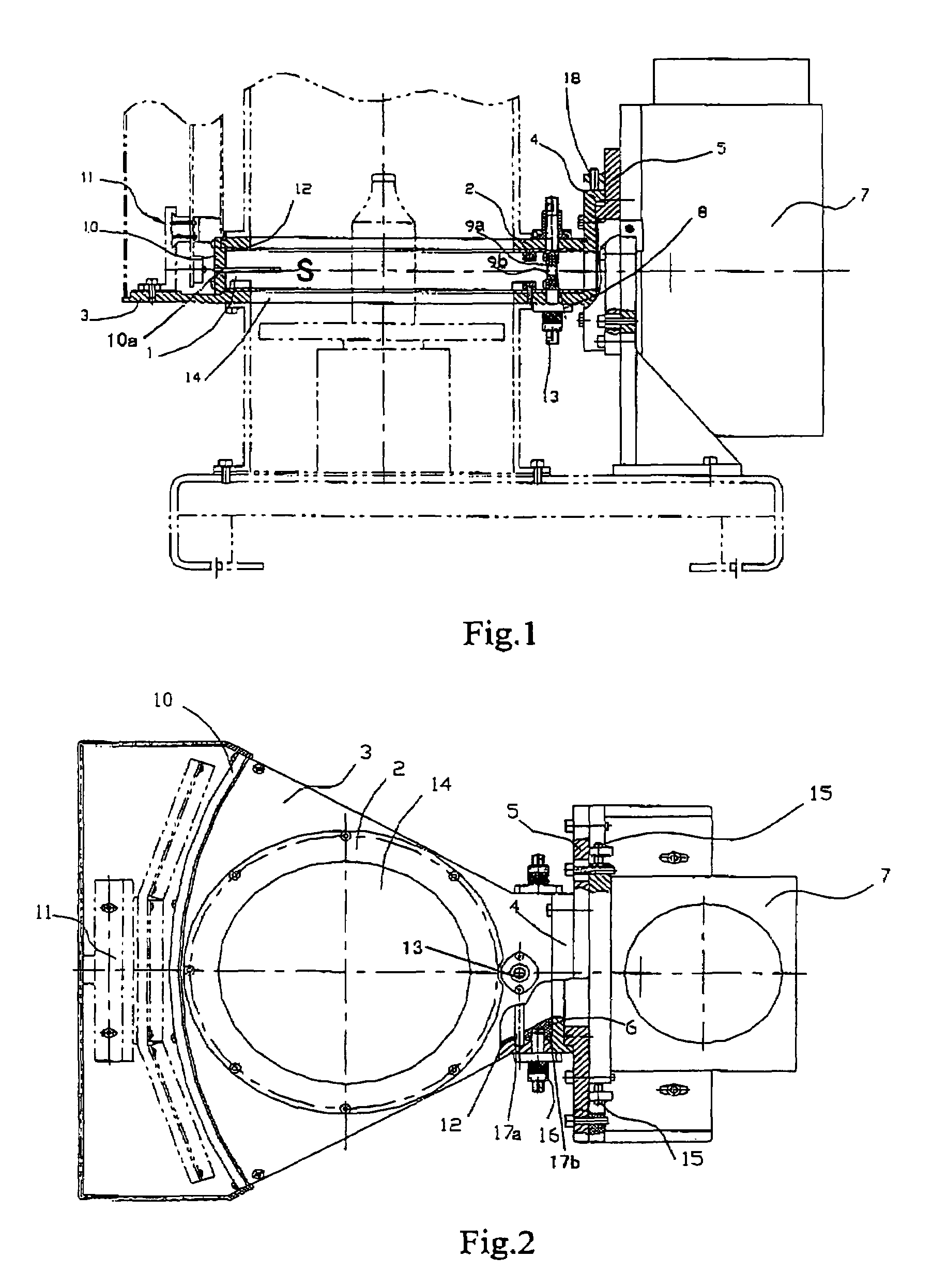
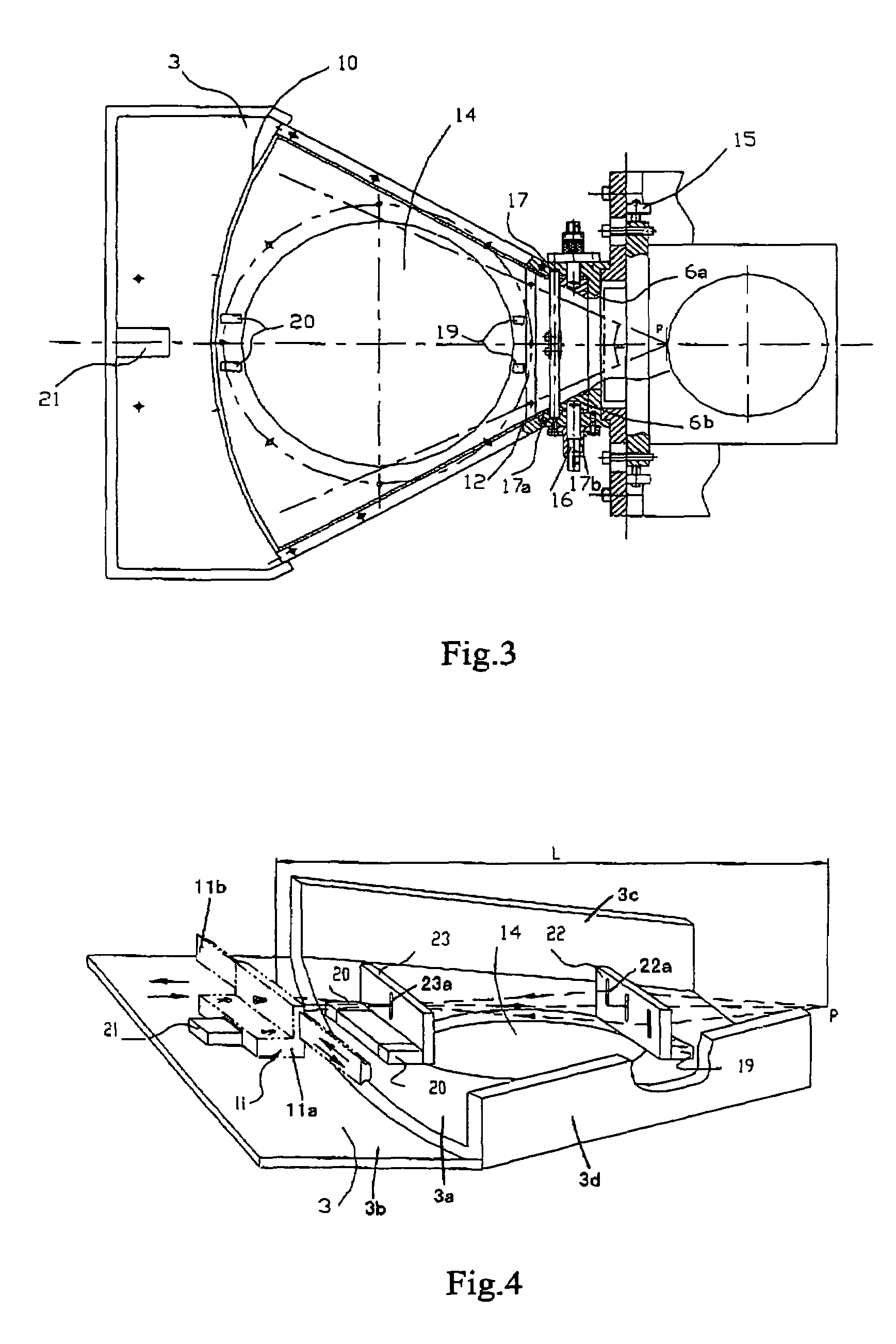
[0031]As shown in FIGS. 1 to 3, the ray beam guiding apparatus according to an embodiment of the present application comprises a ray beam guiding box 1, a first collimator 8 (right collimator in FIGS. 1-3), a second collimator 10 (left collimator in FIGS. 1-3), an engaging member / plate 4, and an adjusting member / plate 5.

[0032]The ray beam guiding box 1 defines an inner space S, and has substantially fan-shaped top and bottom surfaces as well as an open wide end (left end in FIGS. 1-4) and an open narrow end (right end in FIGS. 1-4). The engaging plate 4 is joined to the narrow end of the ray beam guiding box 1, and the adjusting plate 5 connects the engaging plate 4 with a ray ge...


PUM


Abstract

The present invention discloses a ray beam guiding apparatus, comprising a ray beam guiding box having substantially fan-shaped top and bottom surfaces, defining an inner space, and having open wide and narrow ends; an engaging member joined to the narrow end of the box; a first collimator mounted to the box adjacent to the narrow end for adjusting size / shape of the ray beam in horizontal vertical direction; a second collimator having a calibration slit or grill and mounted to the box adjacent to the wide end; and an adjusting member connecting the engaging member and a ray generator to adjust a distance therebetween. The box can adjust size / shape and centering of the ray beam, so that inspection quality can be improved and thickness of the ray shielding layer can be reduced, the box is applicable to a ray inspection system which performs security inspection of liquid articles.

Description

BACKGROUND OF THE INVENTION[0001]The present application is claims priority of Chinese patent application Serial No. 200510086455.0, filed Sep. 22, 2005, the content of which is hereby incorporated by reference in its entirety.[0002]1. Technical Field of the Invention[0003]The present invention generally relates to a ray inspection system for making safety inspection of articles, such as a liquid articles, by using rays, more particularly, to a ray beam guiding apparatus.[0004]2. Description of the Related Art[0005]In conventional ray inspection systems, X-rays are generated by using an X-ray tube. When electrons strike onto a tungsten target at an accelerative speed under a high voltage between the anode and cathode of the X-ray tube, X-rays are generated.[0006]Generally, an X-ray beam is emitted from a focal spot and in the form of conic shape. The profile (e.g. size and / or shape) of the X-ray beam should be limited to different forms according to its different applications. In th...

Claims


Application Information

Patent Timeline
Patent Type & Authority Patents(United States)
IPC IPC(8): G21K1/00G21K1/02G21K1/04
CPCG21K1/025G21K1/04G21K5/04
Inventor LI, YULANLI, YUANJINGCHEN, ZHIQIANGLIU, YINONGMIAO, QITIANWU, WANLONGZHAO, ZIRANLUO, XILEIZHANG, LISANG, BINWANG, HAILIN
Owner NUCTECH CO LTD
Why Eureka
Try Eureka